Measurement Operation (6)
F.Capacitance Measurement
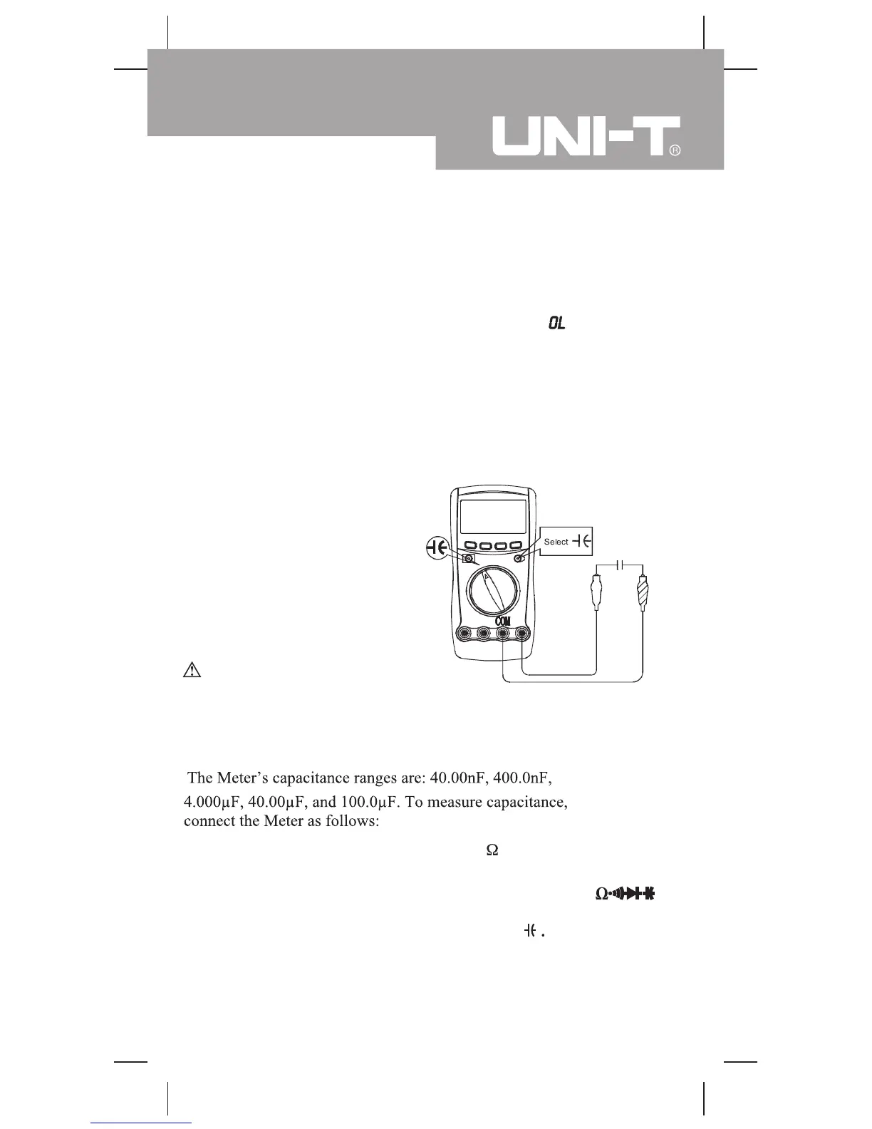
(see figure 8)
voltage drop reading of 0.5V to 0.8V; however, the reverse
voltage drop reading can vary depending on the resistance of
other pathways between the probe tips.
l
Connect the test leads to the proper terminals as said above to
avoid error display. The LCD will display indicating
diode being tested is open or polarity is reversed.
The unit of
diode is Volt (V), displaying the forward voltage drop
readings.
l
When diode testing has been completed, disconnect the
connection between the testing leads and the circuit under
test, and remove the testing leads away from the input
terminals of the Meter.
(figure 8)
Warning
Insert the red test lead into the
HzV
terminal and the black test
lead into theCOM terminal.
2. Model UT60C/UT60E:
Set the rotary switch to
measurement mode.and pressBLUE button to select nF
Model UT60B: Set the rotary switch to
3. Connect the test leads across with the object being measured.
The measured value shows on the display.
Note
l
For testing the capacitor with polarity, connect the red clip to
To avoid damage to the Meter or to the equipment under
test, disconnect circuit power and discharge all high-voltage
capacitors before measuring capacitance. Use the DC
Voltage function to confirm that the capacitor is discharged.
1.
19
Model UT60B/C/E: OPERATING MANUAL
 Loading...