34
Model UT71C/D/E: OPERATING MANUAL
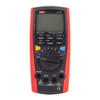
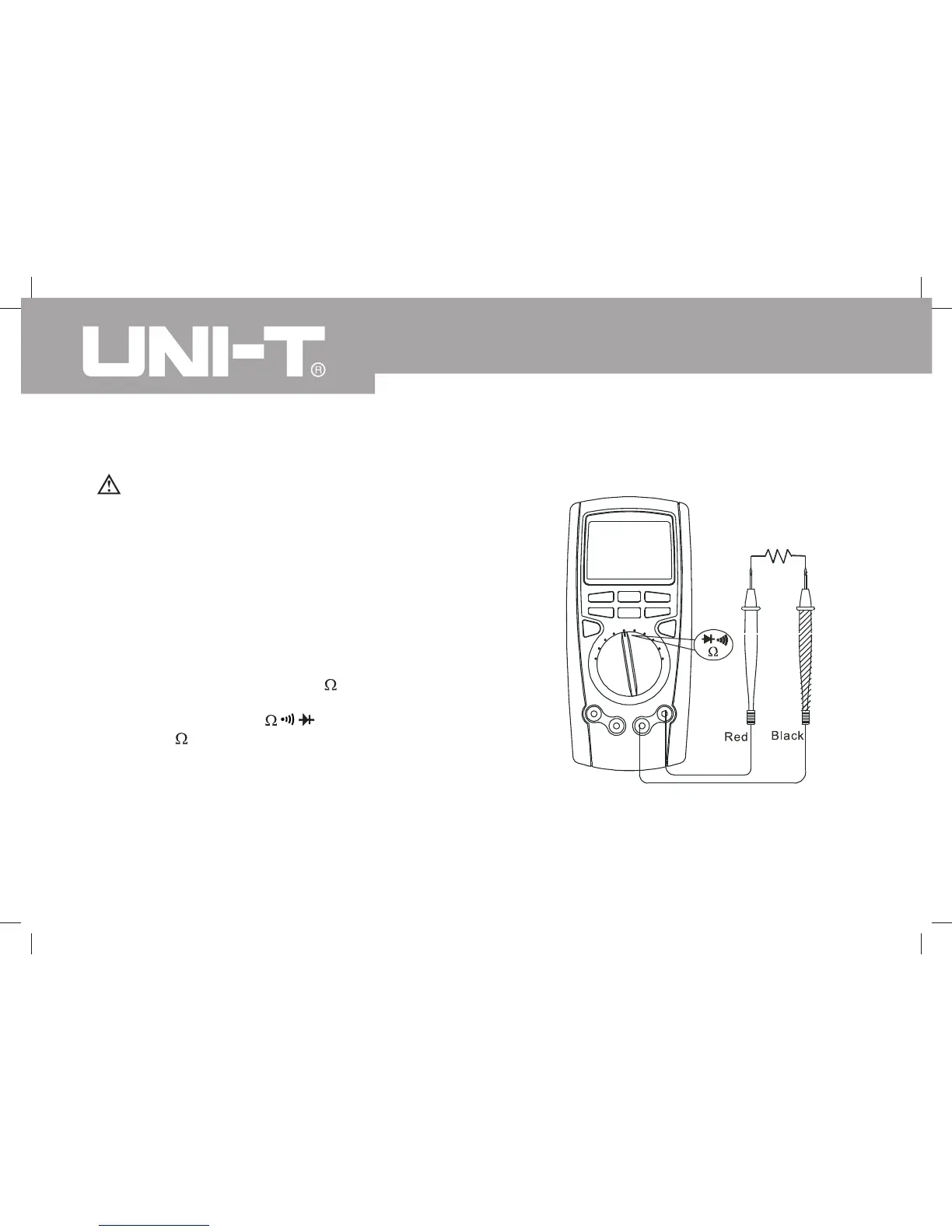
C. Measuring Resistance
Figure 3-3. Resistance Measurement
Warning
To avoid harms to you, please do not attempt to input
voltage higher than 60V DC or 30V rms AC.
To avoid possible damages to the Meter or to the
devices under test, disconnect circuit power and
discharge all the high-voltage capacitors before
measuring resistance.
To measure resistance, set up the Meter as shown in
Figure 3-3 and follow the following procedure:
Insert the red test lead into the terminal and the
black test lead into the COM terminal.
Set the rotary switch to ; press BLUE button
to select measurement mode.
Connect the test leads across with the object being
measured.
The measured value shows on the display.
1.
2.
3.
The BLUE button cycles among resistance, continuity,
and diode.
 Loading...