9
IN-LINE FUSE
A 15A in-line fuse is provided with this fridge in order to protect the
wiring. For 12V operation, use a 15A fuse. A standard automobile
fuse is recommended and the fuse should be wired to the positive
(“+”) side of the system close to the positive battery terminal.
A 15A fuse is provided with this fridge/freezer.
OPERATING VOLTAGE FUSE
12 V 15 A
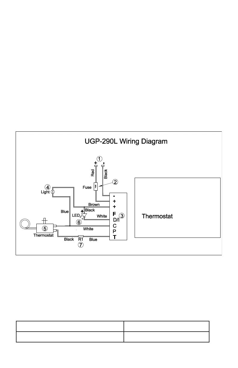
ELECTRICAL DIAGRAM
+ to + and - to -
positive to positive / negative to negative
(red wire) / (black wire)
ATTENTION: Polarity is important in wiring this DC appliance. Be
sure that the positive terminal of the battery or charge controller
coincides with the positive wire to the compressor, and the nega-
tive terminal of the battery or charge controller coincides with the
negative wire to the compressor. The leads should be connected
using cable shoes and screwed connections. Joined leads should be
avoided.
1: Input power 12VDC /24VDC
2: Fuse 15 A
3: Main PCBA cooling unit
4: Interior light
5:
6: Led(Operational errors)
7: R1(Speed selection)
 Loading...