Page 2
RFX-250 INSTALLATION MANUAL
Optimizing Range and Reliability
1. Power on all AV components, dim all dimmers to 50% and power on
anything that may create RF (particularly devices with high speed
microprocessors or hard drives). Observe the RF LED of the RFX-250 by
cupping your hand over it. If it is glowing or flickering you must relo-
cate the RFX-250. If you cannot relocate the RFX-250,
try removing its antenna.
2. Once you have found a location that is absolutely clean
with everything on, test to see if the range is adequate
and that macro reliability is perfect. Start with the
antenna angle set to 45 degrees and positioned so that
the long side of the antenna is facing the customer’s
favorite seating position.
3. When testing, set both the remote and the MRF/MSC to the same
VALID RFID#. Keep in mind that zero (0) is not a valid RFID#. Watch
the STATUS LED on MRF/MSC - it should light every time you press a
button on the remote. This will tell you that the signal was received
and understood. Ignore the RF LED on the RFX-250 (it only indicates
that a signal was received, not that it was understood).
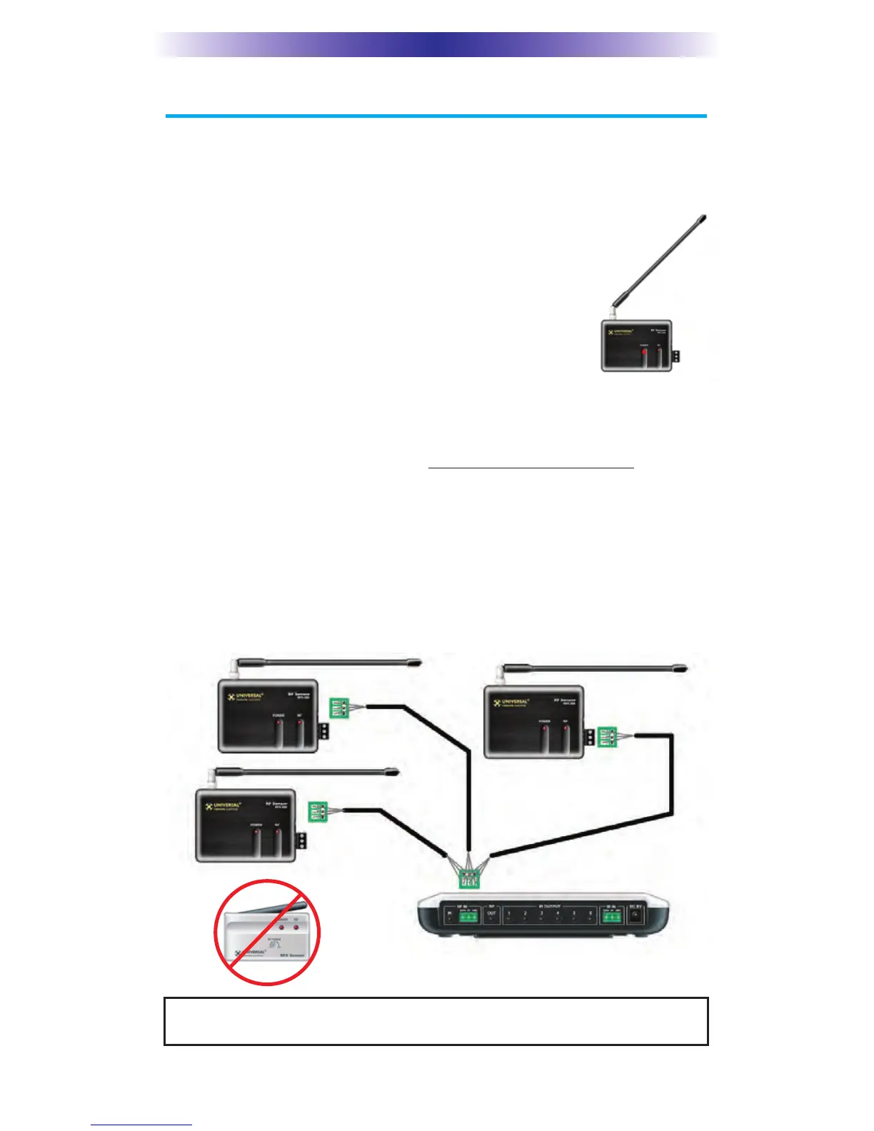
4. If the range is inadequate, you may extend wire to any area that is not
giving good results and place an additional RFX-250 in that area. Up to
three RFX-250’s can be connected to each MRF/MSC.
NOTE: The RFX-250 is ONLY compatible with additional RFX-250s. You
cannot mix RFX-150s in a system with RFX-250s.
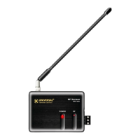
Suggested antenna
angle.
 Loading...