4
DS1716-004A
5
DS1716-004A
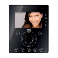
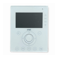
Aiko video door phones Ref. 1716/4 are designed to be used in Ipervoice systems.
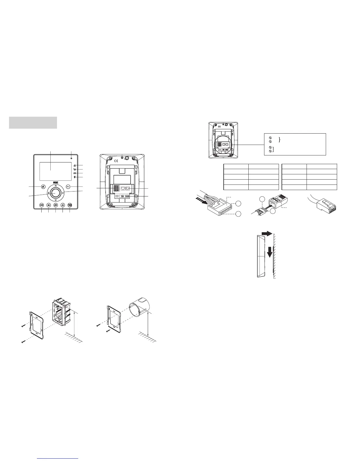
COMPONENTS DESCRIPTION AND CHARACTERISTICS
17
18
3
21
4
5
6
7
16
910111213
14
15
8
ON
1234
ON
12
ENGLISH
Perform connections and dip-switch settings.
Wire No. Wire colour
1
White-Orange
2
Orange
3
White-Green
4
Blue
Wire No. Wire colour
5
White-Blue
6
Green
7
White-Brown
8
Brown
Guide
8
1
Plug
8
1
NO LAN
ON
1234
ON
12
S-
S+
Additional ringer
PANIC Panic input
At the end of programming, fasten the video door phone to the bracket.
1
2
TECHNICAL CHARACTERISTICS
Power supply voltage: ....................................................................................................................48 ÷ 54Vdc
Current consumption in standby: ......................................................................................................1mA max
Max. current consumption: ...........................................................................................................160mA max
Operating temperature range: .....................................................................................................-5°C ÷ +45°C
Compliant with .................................................................................................... EN61000-6-3, EN61000-6-1
1 - Display
2 - Microphone
3 - Indication of “mute function” active (green
led)
4 - Indication of automatic door lock release
active (green led)
5 - Indication of present messages (green led)
6 - Indication of open door or absence active
(red led)
7 - Door lock release button - Contextual button
OK
8 - Navigation buttons
9 - Open main entrance button
10 - Mute ringer button (MUTE)
11 - Switchboard call button
12 - Automatic activation button
13 - Menu button
14 - Loudspeaker
15 - Button used to activate/deactivate audio -
Contextual button X
16 - Terminal pins for connection to additional
ringer and panic button
17 - RJ connectors for connection to the system
18 - Confi guration dip switch (see system
manual)
Aiko video door phone is provided with an embedded device for hard of hearing.
INSTALLATION
Fix the fl ush mounting box at the height shown in the following fi gure.
Fasten the bracket to the embedding box.
1,50m
1,45m
§
 Loading...