10
Lowes.com
EXISTING CONSTRUCTION – INSTALLATION FROM ABOVE WITH SUSPENSION BRACKETS
(ATTIC ACCESSIBLE) ONLY IF UNABLE TO ATTACH DIRECTLY TO THE JOIST(S)
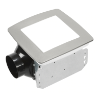
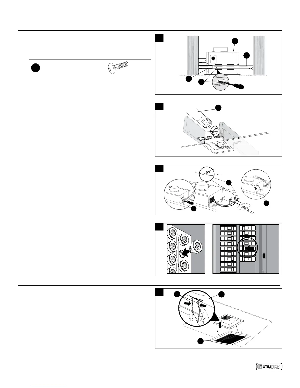
3. Secure the suspension brackets (D, E) to fan body (A)
using short machine screw (BB).
3
BB
A
D
E
Hardware Used
BB
Short machine screw
x 1
4. Connect a 4 in. circular duct (4.1) (not supplied) and vent
to the outside. Secure it with duct tape (not supplied) or
clamp (not supplied) to make connection secure and air
tight.
4
4.1
5. Remove fan junction box cover (5.1). Using quick
connector, connect house wires to fan wires (5.2) as
shown in wiring diagram on page 5. Wire connections
area as follows: black to live switch wire, white to neutral,
green to ground. Reattach fan junction box cover (5.3).
5
Quick
connector
House
wires
Product
wires
5.1
5.2
5.3
6. Turn on the power source. Check fan for any abnormal
sound or vibration.
6
ON
OFF
ON
OFF
ON
OFF
ON
OFF
ON
OFF
ON
OFF
ON
OFF
ON
OFF
ON
OFF
ON
OFF
ON
OFF
ON
OFF
ON
OFF
ON
OFF
ON
OFF
ON
OFF
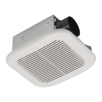
GRILLE INSTALLATION
1. Attach grille (B) by pinching mounting springs (1.1) and
insert into narrow rectangular slots in fan body (A).
1
1.1
A
B
 Loading...