ENGLISH
- 39 -
L Power phase 230 Vac
N Neutral 230 Vac
B1 - B2 Flashing light 230Vac - 40W
B3 - B3 Courtesy light
M1 START - Open command for connecting
traditional devices with N.O. contact
m WARNING: If you use maintained
command devices (magnetic loop detectors,
timers, presence detectors, etc.) clock mode
must be used (parameter Strt = oroL).
M2 START P. - Pedestrian open command for
connecting traditional devices with N.O. contact
m WARNING: If you use maintained
command devices (magnetic loop detectors,
timers, presence detectors, etc.) clock mode
must be used (parameter Strt = oroL).
M3 STOP command. N.C. contact
M4 Common (-)
M5 Photocell 1. N.C. contact
M6 Photocell 2. N.C. contact
M7 Type 1 edges. N.C. contact
M8 Type 2 edges. N.C. contact
M9 Accessories common (-)
M10 24Vac supply for photocells and other
accessories
M11 Accessory power common (-)
M12 24Vac supply - photocell/optical edge TX for
functional Test.
Connect power supply cables of photocells
transmitter between terminals M11 and M12
A1 Antenna shield
A2 Antenna
ADI ADI module interface
RECEIVER Plug-in receiver
FUSE 10A
MAINS It shows that the control unit is power supplied
OVERLOAD It shows that there is an overload on accessories
power supply
4.10 - PLUG IN RECEIVER
PD19 control unit is suitable for plugging in a MR receiver having
a high-sensitivity super-heterodyne architecture.
m WARNING: Pay attention to the way you connect the
removable modules.
MR module receiver is provided with 4 channels and each of
them is suitable for a command of PD19 control unit:
• CHANNEL 1 g START
• CHANNEL 2 g PEDESTRIAN START
• CHANNEL 3 g STOP
• CHANNEL 4 g COURTESY LIGHT
NOTE: Before programming 4 channels and function logics
read carefully the instructions of MR.
4.11 - ADI INTERFACE
The ADI (Additional Devices Interface) interface of the control unit
PD19 allows the connection to V2 optional modules.
Refer to V2 catalogue or to the technical sheets to see which
optional modules with ADI interface are available for this control
unit.
m WARNING: Please read the instructions of each single
module to install the optional modules.
For some devices, it is possible to configure the mode for
interfacing with the control unit; in addition, it is necessary to
enable the interface so that the control unit can process the
signals arriving from the ADI device.
Please refer to the i.Adi programming menu to enable the ADI
interface and access the device configuration menu.
ADI devices use the display of the control unit to issue alarms or
display the configuration of the control unit.
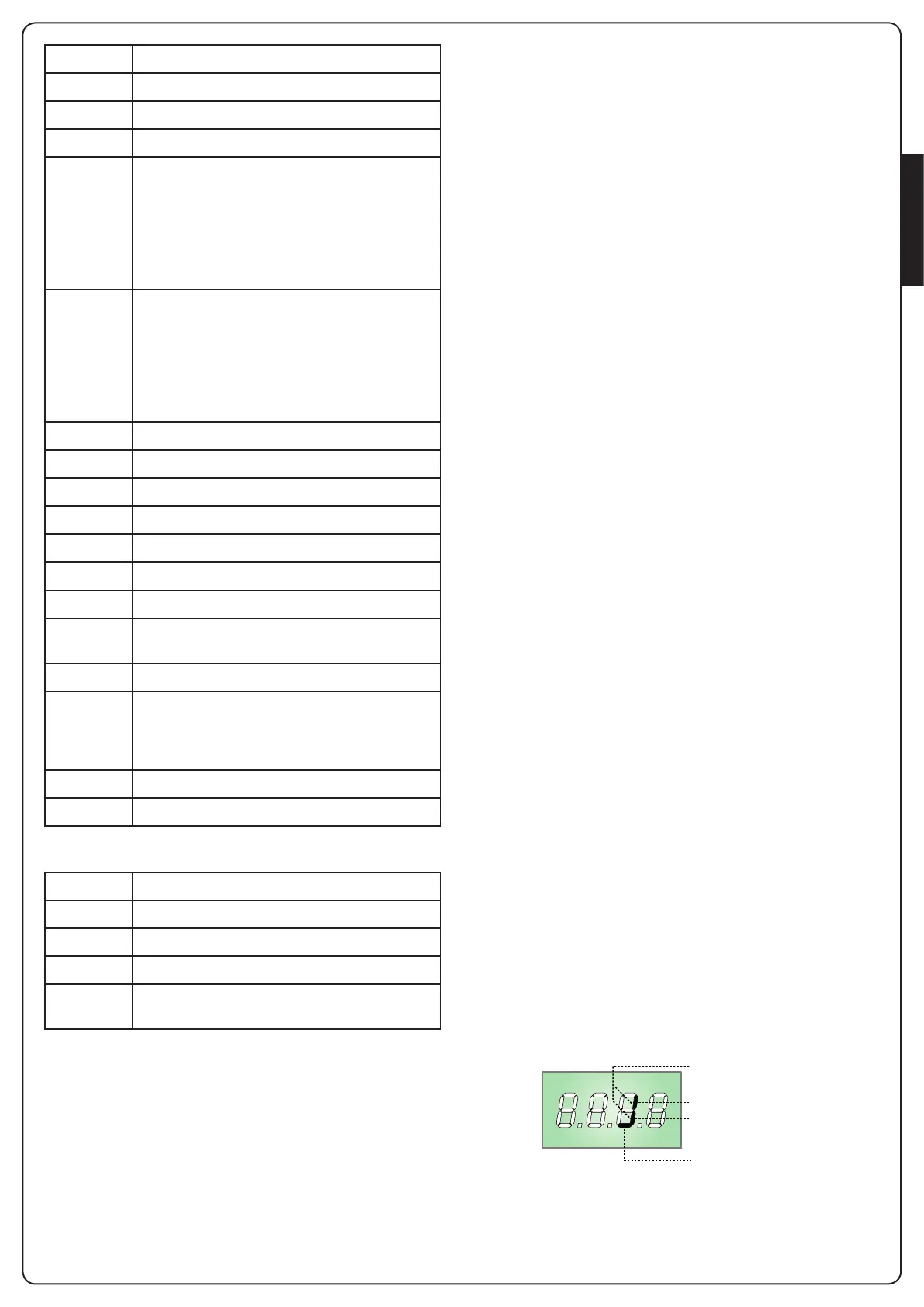
The device connected to the Adi interface is able to signal to the
control unit three alarm signals, which are displayed on the
control unit display as follows:
• PHOTOCELL ALARMS - the upper segment comes on: the gate
stops moving, when the alarm stops opening restarts.
• EDGE ALARM - the lower segment comes on: inverts motion of
the gate for 3 seconds.
• STOP ALARM - both segments start flashing: the gate stops
and cannot restart until the alarm stops.
• SLAVE - segment steadily lit: it is used by the optional module
SYNCRO to indicate that the control unit is configured as
SLAVE.
PHOTOCELL ALARM
STOP ALARM
EDGE ALARM
SLAVE
 Loading...