ENGLISH
9
INSTALLATION
Installation of the control unit, the safety devices and accessories
must be performed with the power supply disconnected.
POWER SUPPLY
The control unit must be powered by means of a 230 V - 50 Hz
or 120 V - 60 Hz power line, depending on the model, protected
by a differential magnetothermal switch in compliance with legal
regulations.
Connect the power cables to the control unit L and N terminals.
MOTORS
The control unit can control one or two asynchronous AC motors.
If the control unit is used to control only one motor, then this
must be connected to the terminals relating to motor 1.
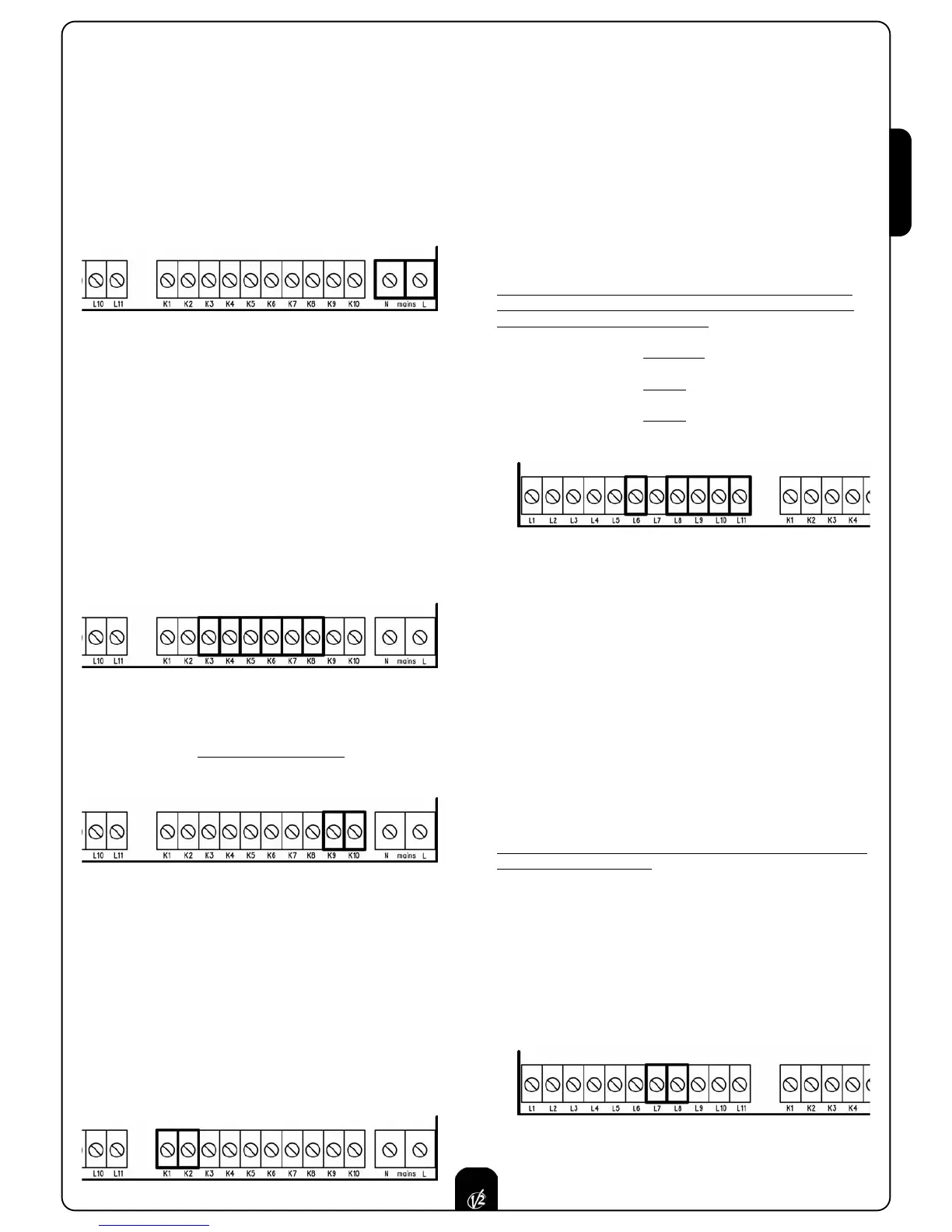
Connect the cables for motor 1 as follows:
• Opening cable to terminal K3
• Closing cable to terminal K5
• Common return cable to terminal K4
• Start-up capacitor between terminals K3 and K5
Connect the cables for motor 2 (if present) as follows:
•
Opening cable to terminal K6
•
Closing cable to terminal K8
• Common return cable to terminal K7
• Start-up capacitor between terminals K6 and K8
BLINKER
The control unit provides for the use of a 230V - 40W or
120V - 40W blinker with built-in intermittence
.
Connect the cables to terminals K9 and K10.
COURTESY LIGHT
This output has a normally-open clean contact relay which closes
for approx. 1 second at the start of an opening phase. This
switch may be used to activate a courtesy light timer (max. load:
230V - 4 A).
PLEASE NOTE: If there is no timer, the courtesy light can be
controlled using channel 4 of r
eceiver MR1: bistable or timer
programmable channel (read the instructions for the receiver MR1
thoroughly).
The switch is on terminals K1 and K2.
PHOTOCELLS
The control unit has a 24VAC power supply for photocells with
switch normally closed, and can perform an operational test
before to starting the gate opening procedure.
The photocell can be used with two settings:
1. Photocell always active:
Intervention of the photocell during opening or closing
causes the gate to stop.
When the photocell restor
es, the gate re-opens completely.
2. Photocell NOT active during opening:
Intervention of the photocell during opening is ignored.
Intervention of the photocell during closing causes the gate
to re-open completely
.
Independently of the setting selected, when the gate is paused
while opening, the time count for any automatic re-closure will
only start after the photocell restores.
• Connect the photocell transmitter power cables between
terminals L10 (GND) and L11 (+) on the control unit.
• Connect the photocell receiver power cables between
terminals L10 (GND) and L9 (+) on the control unit.
• Connect the photocell r
eceiver output between terminals L6
and L8 on the control unit.
SAFETY EDGES
The control unit has an input for controlling safety edges; this
input is capable of controlling standard edges with switch
normally closed and conductive rubber edges with nominal
resistance of 8.2 kOhms.
Edges can be used with two settings:
1. Edge always active:
Intervention of the edge during opening or closing causes
inversion of the direction of movement in order to free the
body that caused the edge to intervene.
The gate stops after appr
ox. 3 seconds.
2. Edge NOT active during opening:
Intervention of the edge during opening is ignored.
Intervention of the edge during closing causes the gate to
re-open completely
.
Independently of the settings selected, any subsequent automatic
re-closure will be cancelled.
Standard edge with switch normally closed: connect the
edge cables between terminals L7 and L8 on the control unit.
In order to satisfy the r
equirements of standard EN12978, it is
necessary to install safety edges with a control unit which
constantly monitors correct operation. If control units are used
with the option of running tests by means of interrupting the
power supply, connect the control unit power supply cables
between terminals L10 (GND) and L11 (+).
 Loading...