PORTUGUÊS
- 32 -
1 1D
E
3
A
C
2
56
4
FIG.1
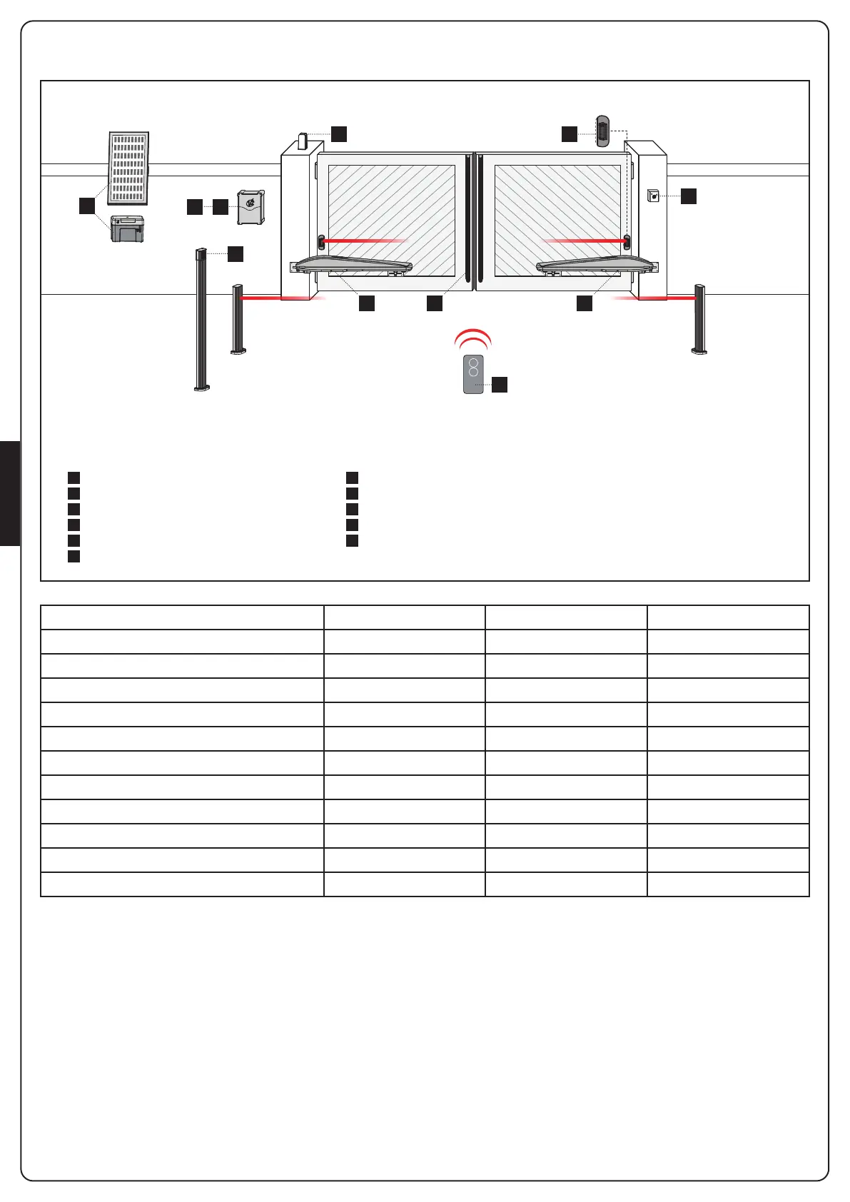
ESQUEMA DE INSTALAÇÃO
A
B
C
D
E
1
2
3
4
5
6
Selector de chave
Fotocélulas para colunas
Selector digital via rádio em coluna
Barras de segurança
Sistema ECO-LOGIC (só com STARK3-24V e CITY2+BC)
Atuador
Quadro elétrico
Emissor
Módulo receptor
Fotocélulas
Pirilampo
COMPONENTES ACESSÓRIOS ADICIONAIS
CABOS PARA UTILIZAR < 10 metros de 10 a 20 metros de 20 a 30 metros
Alimentação elétrica 230V 3G x 1,5 mm
2
3G x 1,5 mm
2
3G x 2,5 mm
2
Alimentação elétrica motore 230V 4G x 1,5 mm
2
4G x 1,5 mm
2
4G x 2,5 mm
2
Alimentação elétrica motore 24V 2G x 1,5 mm
2
2G x 1,5 mm
2
2G x 2,5 mm
2
Fotocélulas (TX) 2 x 0,5 mm
2
2 x 0,5 mm
2
2 x 0,5 mm
2
Fotocélulas (RX) 4 x 0,5 mm
2
4 x 0,5 mm
2
4 x 0,5 mm
2
Selector de chave 2 x 0,5 mm
2
2 x 0,5 mm
2
2 x 0,5 mm
2
Barras de segurança 2 x 0,5 mm
2
2 x 0,5 mm
2
2 x 0,5 mm
2
Pirilampo 2 x 1,5 mm
2
2 x 1,5 mm
2
2 x 1,5 mm
2
Antena (integrada no pirilampo) RG174 RG174 RG174
ECO-LOGIC (box bateria) 2 x 1,5 mm
2
- -
ECO-LOGIC (painel) 2 x 1 mm
2
- -
 Loading...