ENGLISH
- 36 -
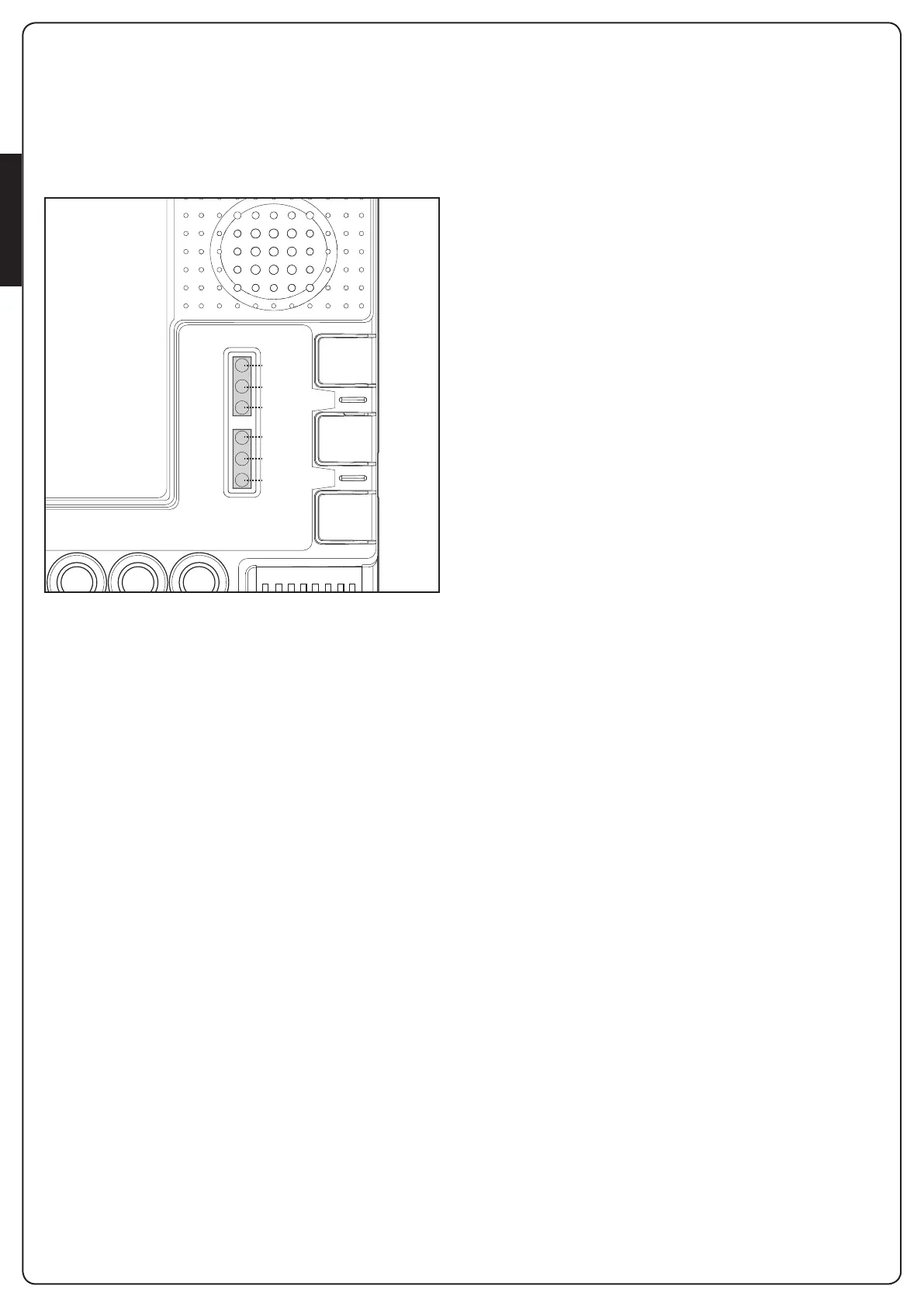
9. LED SIGNALLING
With the control unit powered up (if control unit protection is
not activated) the yellow Set led flashes for 5 seconds and, if
everything is correctly hooked up, the red “Photo” and “Stop”
leds turn on to indicate that the two safety contacts are closed.
The yellow Set LED is exclusively reserved for programming.
1 2 3 4 5 6 7 8
C
M
VH
VRE F
VL
PH 01
PH 02
GND
+ VA
GS I
OL 1
CL 1
OL 2
CL 2
ST R
GND
GND
ST P
PED
ANT
GND
AUX
C
M
N L
HAZ
TRANSF
PRI M
START
RADIO
SET
ERROR
STOP
PHOTO
START
RADIO
SET
9.1 - INPUT STATUS SIGNALLING LEDS
The following signals refer to the control unit in standby mode,
that is, powered and inactive for 12 seconds (not during
programming).
GREEN PHOTO LED:
- ON in the fixed mode if the PHO1 and PHO2 contacts are
closed
- OFF if at least one of the PHO1 or PHO2 contacts is opened
GREEN STOP LED:
- on in the fixed mode if the STOP contact is closed
- off if the STOP contact is open
GREEN START LED:
- on in the fixed mode if the START contact (terminals 15-16) is
closed
- off if the START contact (terminals 15-16) is open
RED RADIO LED:
- flashes when a command is received through King Gates
transmitter
- is off when the control unit is in standby mode
9.2 - ERROR SIGNALLING LEDS
RED “ERROR” LED:
The red “error” LED signals any errors that hamper the correct
operation of the PCB.
With the control unit in standby mode, the error type is signalled
with a series of flashes at regular intervals (1-second pause
between two successive series) according to the following
scheme:
1 flash: On-board memory damaged
2 flashes: Photo-test of safety devices failed.
See Paragraph 11.1 for solving the problem.
3 flashes: Path programming requested.
See Paragraph 8
4 flashes: Input “PHO2” set as a resistive edge and check failed.
See Paragraph 11.3 for solving the problem
GREEN START LED:
If, when START on the board is pressed or a control signal is sent
by wire, the green led flashes three times without the system
executing the manoeuvre, then “wire controls blocked” is
enabled: see par. 12.2.
GREEN START LED, RED RADIO LED AND YELLOW SET LED:
If, when attempting to enter into any programming scheme, the
set, radio and start LEDs flash fast three times, it means that the
“control unit protection” is active.
See Paragraph 13.1 for solving the problem.
 Loading...