Dedicated Outdoor Air Unit32
Optional Energy Wheel – Troubleshooting
Symptom Possible Cause Corrective Action
Energy wheel
does NOT
turn
Air seals are too tight.
Refer to Adjust the Air Seals in the Optional Energy Wheel
Start-Up section.
Broken belt. Replace.
No power to wheel motor. Make sure wheel drive is plugged in. Verify power is available.
Energy
wheel runs
intermittently
Wheel motor overloads are
tripping due to rubbing between
wheel and air seals.
Recheck air seals, make sure they are not too tight. See Adjust
the Air Seals in the Optional Energy Wheel Start-Up section.
Troubleshooting – Alarms
Several of the electronic controls in the unit monitor the
system for faults and will go into alarm, shutting down
the unit or a single function within the unit.
Microprocessor Controller
The microprocessor is located in the main control
center. If the microprocessor is in alarm condition,
the Alarm button will blink red. Press the Alarm
button to see the specific condition or to reset the
microprocessor. Refer to the microprocessor IOM for
detailed information on fault codes and see the unit-
specific wiring diagram.
Phase Monitor
The phase monitor has two LED indicator lights, one
red and one green. Green indicates proper operational
status, red indicates the unit has detected a fault and is
in alarm condition. The alarm LED will blink to show the
specific fault and there is a chart printed on the monitor
that shows the code for the blinking light. The phase
monitor is self-resetting once the alarm condition is
corrected. It is located in the main control center.
Variable Frequency Drive (VFD)
Variable frequency drives have a display screen that will
show an alarm condition. If a fault such as a voltage
spike occurs, the VFD will go into alarm and will not
reset until a hard restart is performed. See the unit-
specific manufacturer’s manual supplied with the unit.
VFDs are located in the main control center.
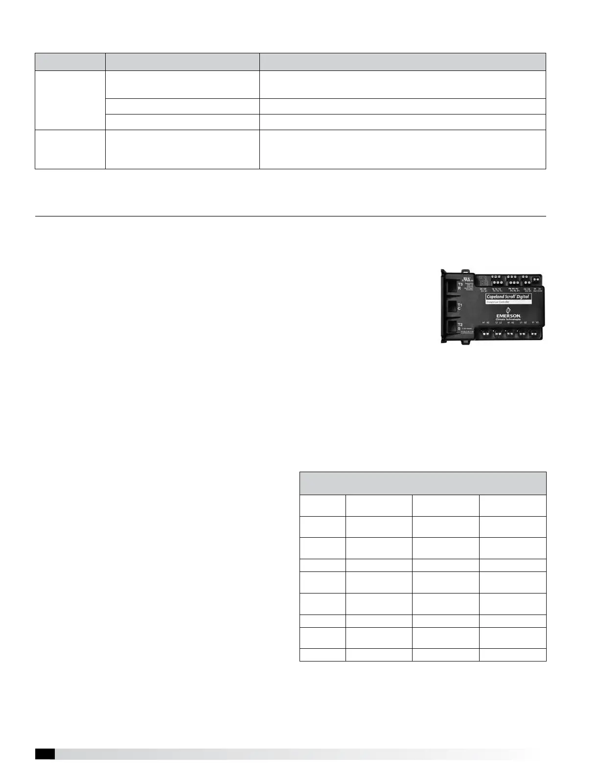
Optional Digital Scroll Compressor
Controller
Present only if packaged DX with digital scroll option is
selected. The controller has
three LED indicator lights.
One is green, indicating that
it has power, one is an alarm
indicator that will flash a code
for various alarm conditions
and the third indicates
whether the compressor
is operating in a loaded or unloaded condition. See
the manufacturer’s unit-specific manual for further
information.
See the Fault Code chart below. The Fault Code chart
is also printed on the back of the controller. Note that
if the controller generates either a Code 2 or a Code 4
Lockout, a manual reset must be performed. Manual
Reset is accomplished by shutting off main power to the
unit and then turning it back on.
Digital Scroll Compressor
Controller Fault Codes
Alert Code
System
Condition
Diagnostic
Alert Light
Action
Code 2*
High Discharge
Temperature Trip
Blinks 2 Times Lockout
Code 3
Compressor
Protector Trip
Blinks 3 Times Lockout
Code 4* Locked Rotor Blinks 4 Times Lockout
Code 5
Demand Signal
Loss
Blinks 5 Times Lockout
Code 6
Discharge
Thermistor Fault
Blinks 6 Times
Reduce
Capacity
Code 7 Future N/A N/A
Code 8
Welded
Contactor
Blinks 8 Times
Unload
Compressor
Code 9 Low Voltage Blinks 9 Times Trip Compressor
*Protective faults that require manual reset.
 Loading...