Installation Guide Repeater Installation
25
d. Assemble the cover onto the enclosure, tightening the screws in a couple of turns each. Using an
alternating ‘X’ pattern, continue to tighten the screws until they are all tight.
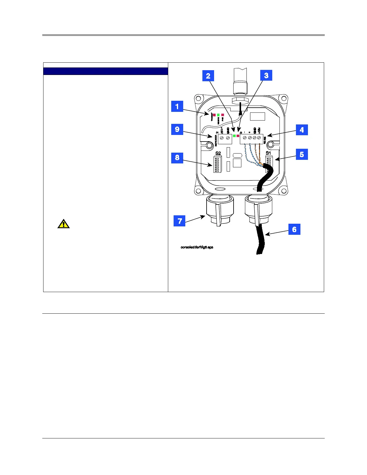
LEGEND FOR NUMBERED BOXES IN FIGURE 24
RECEIVER
1. RS-485 Comm Activity
XMIT (Red) LED – flashes when message
transmitted to TLS-RF
RCV (Green) LED – flashes when message
received from TLS- RF
PWR (Red) LED – receiver power-on indicator
2. Green LED – Unit status
3. Red LED – Radio status
4. Connect the like color pairs of the RS-
485/power cable to the same RS-485
terminals in both the receiver and the master
TLS RF (ref. Figure 6 on page 11).
5. S1 DIP switch
6. RS-485 cable
7. A solid bushing must be installed to seal the
receiver when this cord grip is unused. In sites
where a repeater is powered from the receiver,
the repeater’s power cable enters through this
cord grip and attaches to item 9.
Hand tighten both cord grip nuts to
prevent water entry!
8. S2 DIP switch
9. +15 Vdc power source for the repeater.
Figure 24. Wiring the receiver
Repeater Installation
1. One repeater is installed per site which relays transmitter signals to the site’s receiver. The repeater is
mounted in a vertical position on same side of the building as the receiver (preferably), and in a direct line
of sight with the receiver (ref. Figure 17 on page 18).
2. The repeater is attached to its mounting bracket with #10 x 1/2” taptite screws from its install kit (ref.
Figure 23 on page 24). The L-bracket is then mounted on the outer wall of the building using appropriate
fasteners (customer supplied).
3. Note the cover of the repeater indicated the cord grip to be used for the cable connecting the repeater to
its dc power source. Loosen the +15 Vdc labeled cord grip, then remove the cover of the repeater and
set it aside. Push the 2-wire power cable through the power cable cord grip and into the Repeater.
4. Set S1 and S2 as desired (refer to Appendix C).
5. Connect the 2-wire dc power cable to the repeater terminal block white to +15 and black to GND (see
item 7 in Figure 25).

 Loading...