19
EN
Description
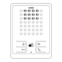
Electronic units 13F4 (audio) and 13F7 (video) can be used only in Due Fili Plus systems.
They are equipped with an alphanumeric keypad and the video version has a camera with a white LED lighting unit.
Electronic units 13F4 and 13F7 can be used as replacements in systems equipped with electronic units art. 12F4, 12F7. For entrance panels 89F4, 89F7 the
spare part is functional, not mechanical. Electronic units 13F4 and 13F7 can also be used in conjunction with traditional push-buttons. Up to two additional
button modules can be connected on single wire, art. 12TS, or one additional button module on 2-wire, art. 12TD.
Technical characteristics
- 1/4" CCD sensor (13F7)
- Minimum illumination 1.0 lux (13F7)
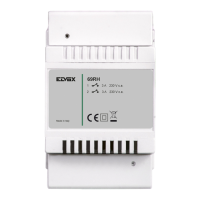
- Power via terminals B1, B2.
- Power via terminals Ext+, Ext- if the electronic unit needs to be powered via an additional power supply.
- Video signal output 16 dBm
- Current draw in standby 120 mA
- Current draw during communication 320 mA
- Current draw during communication and lock activation 470 mA
- Minimum voltage 24 V d.c. measured at terminals B1, B2
- Lens adjustable by hand, vertically and horizontally (13F7)
- Operating temperature: -10 °C / +55°C.
Electronic units 13F4 and 13F7 are suitable for both VERTICAL BUS and HORIZONTAL BUS installation. The default configuration is VERTICAL INSTAL-
LATION and features management of up to 200 users. The HORIZONTAL INSTALLATION configuration features electronic units that fully manage up to
1000 users each.
NOTE: The values indicated in square brackets refer to the "HORIZONTAL INSTALLATION” configuration.
1 2 3
4
5
6
7 8 9
0
ABC DEF
GHI
JKL
MNO
PQRS
TUV
WXYZ
+
R
3
2
1
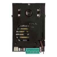
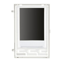
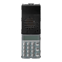
Electronic unit
Wiring for connection
of additional button
modules
PRG buttonRESET
Wiring
for connection
terminal block
Figure 1
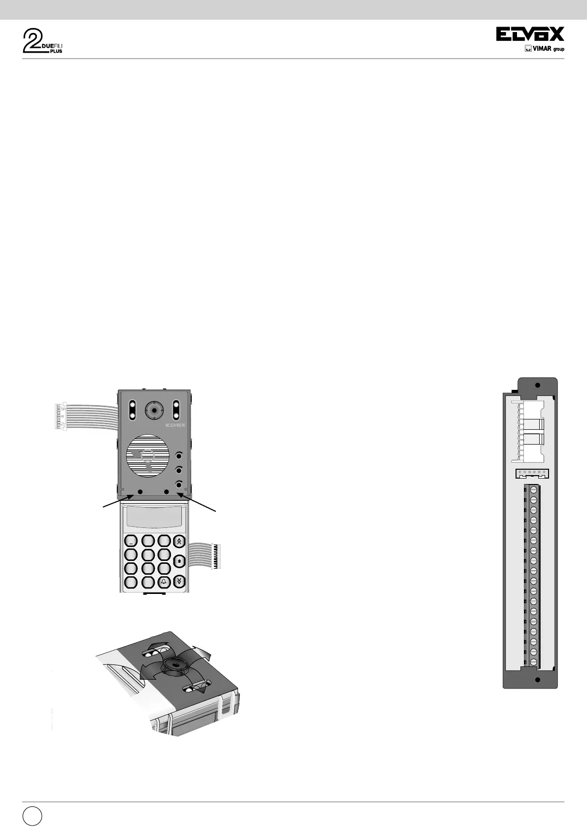
Figure 2
Terminal block
CN1) Connector for electronic unit.
CN2) Connector for programmer art. 950C or inter-
face art. 692I/U or art. 692I.
B2) Bus (cable riser).
B1) Bus (cable riser).
EXT+) External power supply (+ art. 6923).
EXT-) External power supply (- art. 6923).
VLED)
LED power supply for additional modules.
X) Video input (coaxial core) for external camera
(13F4).
M) Video input (coaxial sheath) for external ca-
mera (13F4).
PA) Input for door open sensor (with reference to
terminal M).
CA) Door open command (with reference to termi-
nal M).
M) Ground.
S+) Lock output 12Vdc (+) (see note below).
S-) Lock output 12Vdc (-) (see note below).
+12V) Output +12V (max 120 mA) with current limi-
ter.
-L) External camera pilot, open collector output
(13F4).
SR) Relay-operated lock pilot, open collector
output.
F2) Relay-operated F2 function pilot, open collec-
tor output.
F1) Relay-operated F1 function pilot, open collec-
tor output.
M) Ground.
B2
B1
EXT+
EXT-
VLED
M
PA
CA
M
S+
S-
+12V
-L
SR
F2
F1
M
X
B2
B1
EXT+
EXT-
VLED
M
PA
CA
M
S+
S-
+12V
-L
SR
F2
F1
M
X
CN2
CN1
CS2411 250105
Figure 3
Note: S+/S- outputs. The entrance panel supplies a
current peak of I
T
> 1A for 10 ms, followed by a holding
current of I
M
= 200 mA for the entire duration of the lock
command (see lock time).
Manual adjustment
horizontal and vertical
 Loading...