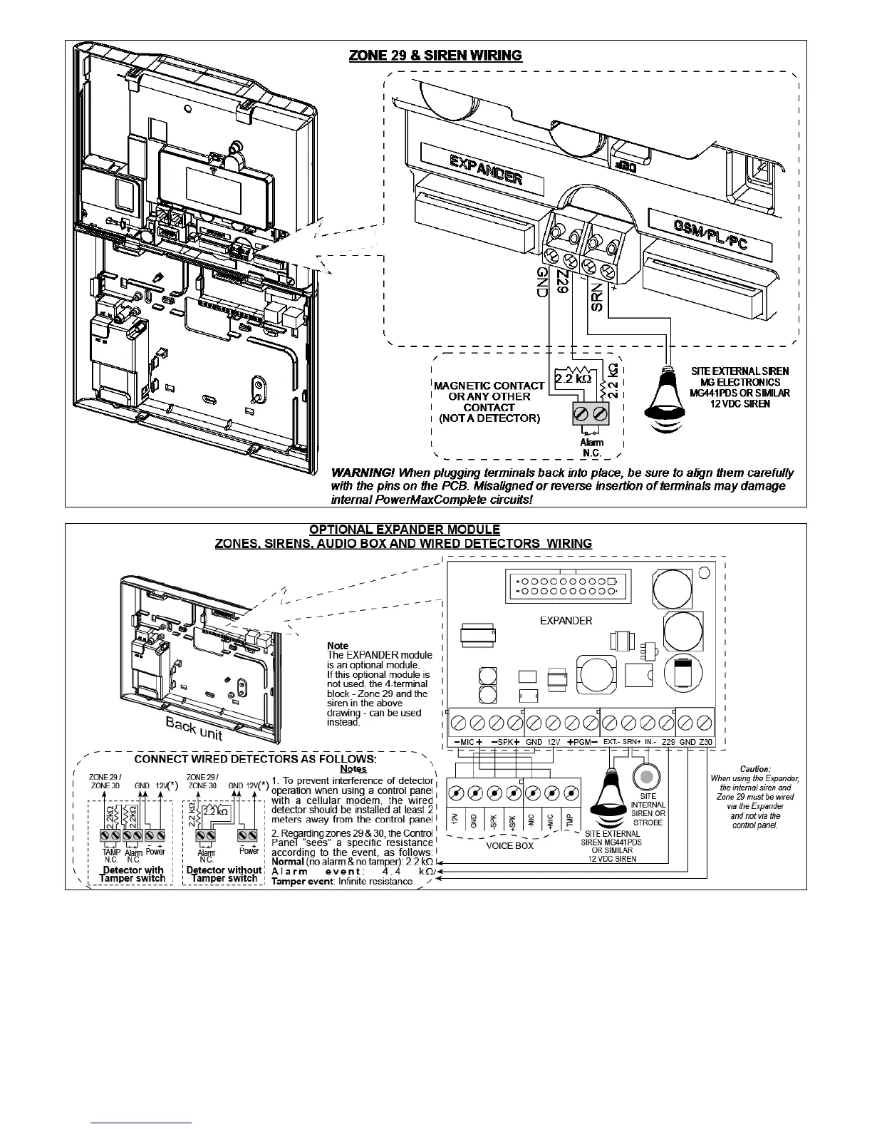
Figure 3.2 - Wiring
Notes for EXPANDER module wiring:
* Zone 29/GND and Zone 30/GND terminals can be
connected to a normally closed contact of a detector,
switch (for example a Tamper switch of any device), or
a pushbutton, via a 2.2 K
resistor. The 12V terminal
can be used to supply 12V (up to 450mA) to wired
detectors (if necessary).
** The EXT terminal can be used to trigger an external
siren.
The INT terminal can be programmed for an "internal
siren" or "strobe" (see DEFINE OUTPUTS - DEFINE
INT/STRB in par. 4.8).
The 12V and "GND" terminals can be connected to a
siren (for constant DC power supply).
IMPORTANT! Total PowerMaxComplete output current (of
INT & EXT sirens, PGM output and detectors) must not exceed
550 mA for 9.6V battery and 450 mA for 7.2V battery.
 Loading...