Group 37 Wiring diagram FL6 Example of wiring diagram
Example of wiring diagram
T3009608
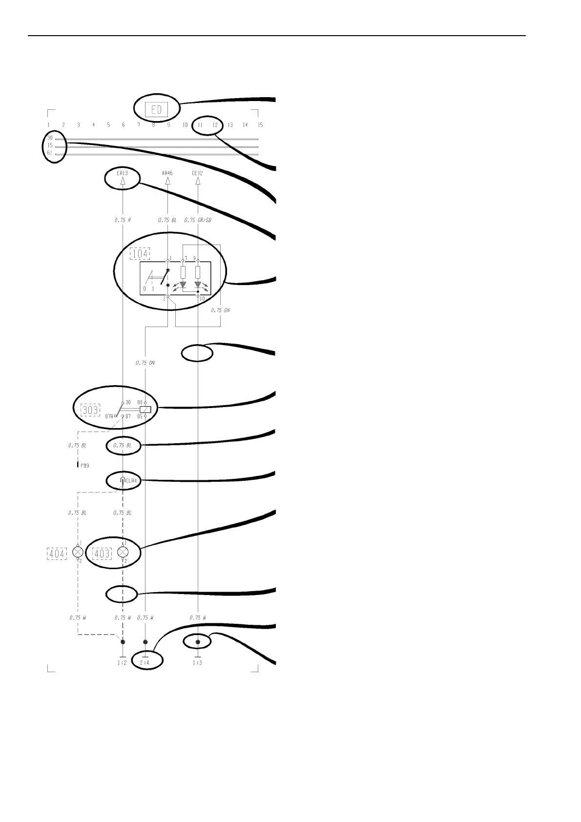
Refer to the list of contents for the designation of the
circuit diagram. If the circuit diagram designation is
boxed in with broken lines this means that the circuit
diagram is not standard on all market or vehicle models.
Seek column.
30 Voltage battery, kl.30.
15 Voltage with starting key in drive position, kl.15.
61 Voltage when alternator charges, kl.61.
Reference arrow (for circuit diagram EA, seek column
13).
Switch, comp. no. (104).
Single lines, cables.
Relay, comp. no. (303).
Cable area and colour (0.75 mm² blue).
Connector (CLA terminal 4).
Bulb, comp. no. (403)
A broken line box round the component number shows
that the component is not standard on all markets or
vehicle models.
If the line is broken this means the cable is not standard
on all markets or vehicle model.
Earth connection point no: 2. and earth terminal no: 4.
(see diagram Earth Connections).
Joint sleeve.
2

 Loading...