28
Please Do Not Return This Product To The Store. Contact your local Wayne-Dalton dealer. To find your local Wayne-Dalton dealer, refer to your
local yellow pages/business listings or go to the Find a Dealer section online at www.wayne-dalton.com
Tools Needed:
Tools Needed:
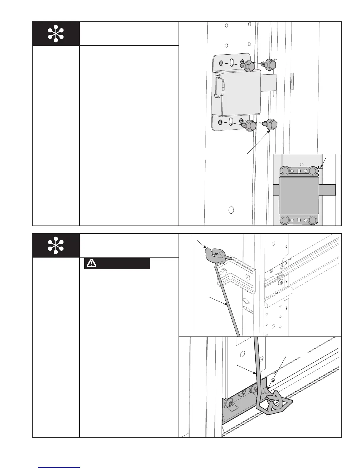
DO NOT INSTALL PULL ROPES
ON DOORS WITH ELECTRIC
OPERATORS. CHILDREN MAY
BECOME ENTANGLED IN THE
ROPE CAUSING SEVERE OR
FATAL INJURY.
Measure and mark the jamb
approximately 48” to 50” (1220 to 1270
mm) from floor on the right or left side
of door. Drill 1/8” pilot hole for No. 6
screw eye. Install the No. 6 screw eye.
Tie the pull rope to the No. 6 screw eye
and to the bottom bracket as shown.
Side Lock
Install the side lock on the second
section of the door. Secure the lock to
the section with (4) 1/4”- 20 x 11/16”
self drilling screws. Square the lock
assembly with the door section and
align with the square hole in the vertical
track. The side lock should be spaced
in approximately 1/8” from the section
edge.
IMPORTANT: SIDE LOCKS MUST BE
REMOVED OR MADE INOPERATIVE IN
THE UNLOCKED POSITION IF AN
OPERATOR IS INSTALLED ON THE
DOOR.
NOTE: After completing this step,
continue with step 7 on page 16.
Power Drill
7/16” Socket
Driver
(4) 1/4”- 20 X 11/16”
SELF DRILLING SCREWS
1/8”
Pull Rope
NO. 6 SCREW EYE
PULL ROPE
BOTTOM BRACKET
PULL ROPE
WARNING
Power Drill
1/8” Drill Bit
 Loading...