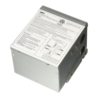
To install the T-57 transfer switch follow the steps below:
Incoming Shore Power:
1. Connect the black wire from the shore cord to the L1 position on transfer switch marked
Power Cord.
2. Connect the white wire from the shore cord to the Neutral position on transfer switch
marked Power Cord.
3. Connect the red wire from the shore cord to the L2 position on transfer switch marked
Power Cord.
4. Connect the ground (copper) wire from the shore cord to the ground block on transfer
switch below that segment.
Incoming Generator Power:
5. Connect the black wire from the generator to the L1 position on transfer switch marked
Generator.
6. Connect the white wire from the generator to the Neutral position on transfer switch
marked Generator.
7. Connect the red wire from the generator to the L2 position on transfer switch marked
Generator.
8. Connect the ground (copper) wire from the generator to the ground block on transfer
switch next to that segment.
Power Output to Panel:
9. Connect the black wire from the Distribution Panel to the black wire L1 on transfer switch
marked Control Panel.
10. Connect the white wire from the Distribution Panel to the white wire (neutral) on
transfer switch marked control Panel.
11. Connect the red wire from the Distribution Panel to the red wire L2 on transfer switch
marked control Panel.
12. Connect the ground (copper) wire from the generator to the ground block on transfer
switch next to that segment.
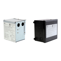
Snap the cover in place on the enclosure to complete the wiring procedure.
Note: All eld connections should be made using 8 AWG (min.) solid or stranded copper
wire rated 75°C (167°F)minimum. Torque terminal strip lugs and Ground block terminals
to 35 in-lb maximum. Caution: over torquing will cause wire and screw damage.
When removing the T-57R Transfer Switch, reverse the order of steps 1 through 12.
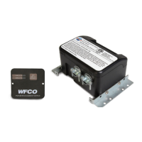
TROUBLESHOOTING INSTRUCTIONS
Troubleshooting the T-30 & T-57R Transfer Switches
Refer troubleshooting to a qualied service technician. Contact the Power PROs at
877-294-8997 for assistance.
7
 Loading...