10
Connection diagram
Position of the connections
A
Water out
(softened water);
G ¾" external thread
B
Water supply (raw water)
G ¾" external thread;
min. 2.5 bar; max. 6 bar;
max. 60 °C;
max. 45°dH total hardness
C
Regeneration water
½ " hose; 2000 mm long
D
Safety overflow
½ " connection
Connection diagram
INFO
Pos. 1 to 4 and pos. 6 are not included in the scope of supply
A water safety device (pos. 4) must be used in order for the softener to be operated in accordance with DIN requirements. A kit is
available from Winterhalter for this purpose.
The kit contains a backflow preventer type HD in accordance with DIN EN 1717.
National installation and operating regulations must also be complied with.
The system can also be mounted in mirror image. Provide on-site connections next to the device.
6 Waste water funnel with trap
5 Hose to warewasher
4 Water safety device
3 Supply hose; 2 x G 3/4" union nut
2 Dirt trap; 1 x G 3/4" union nut; 1 x G 3/4" external thread
1 Water stop cock on-site, G 3/4" external thread
89013537-00
Connection diagram
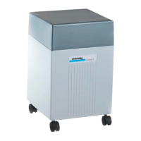
DuoMatik 3 softener
Prepared: 07.02.2017 sch
View from rea
View from front
If space is limited, the water safety device (pos. 4) can also be
installed in the water pipe somewhere else.
Note:
- Top edge of the combination connector must be at least
110 mm above the top edge of the device
- Vertical installation position
- Install in direction of flow

 Loading...