assembly from the appliance. See Fig. 28. When refitting the
hood ensure that the rear return edge passes under the lip at the
rear of the combustion chamber.
(g) Combustion Chamber Front and Sides. Remove the inner
casing cover and flue hood assembly. Unscrew the two wing
nuts securing the front and sides and remove from the
appliance. See Fig. 28.
(h) Burner Assembly. Remove the combustion chamber front
and sides. Pull off the two spark electrode leads and disconnect
the flame sense lead. Undo the G
3
/
4
inch nut on top of the gas
valve. Undo the burner fixing screw. Lift up and remove the
burner assembly from the appliance.
14. 4 SERVICE OF COMPONENTS
Clean the Fan.
Any dust or fluff should be removed with a soft
brush or by blowing. Take care not to distort the pressure
sensing device.
Clean the Main Burner. Brush the blade tops and mixing tube
with a soft brush and check that all the flame ports are clear.
Remove any blockages with a non-metallic brush. Inspect the
injector and clean with a soft brush. Replace the injector if it
appears damaged. Do not use a wire brush or anything likely to
cause damage. Replace the spark and sense electrodes if they
appear damaged.
Clean the Gas to Water Heat Exchanger. Cover the burner
manifold hole in the combustion chamber bottom panel with a
cloth. Clean the heat exchanger using a soft brush. Remove the
deposits from the bottom of the combustion chamber. Do not
distort any of the blades.
Combustion Chamber Insulation. Examine and replace any
pads that are damaged. Remove any dust or deposits using a
soft brush.
Reassemble the appliance in the reverse order.
Check that all components are in place and correctly fixed. Leave
the cabinet front panel to be fitted after checking the operation
of the appliance.
14. 5 TEST THE APPLIANCE
On completion of the service and reassembly of the appliance,
check for gas soundness and the correct operation of the
appliance as described in Section 12 – Commissioning.
Refit the cabinet front panel and reset the controls to the users
requirements.
15.1 IMPORTANT
Switch off the electricity and gas supplies before replacing any
components. After the replacement of any components, check
for gas soundness where relevant and carry out functional
checks as described in Section 12 – Commissioning.
15.2 COMPONENT ACCESS
To replace components it is necessary to remove one or more
sections of the cabinet and cover plates within the appliance as
described in Section 14.3. The facia panel may also need to be
hinged down as described in Section 14.3 (c).
15.3 DRAINING THE APPLIANCE
Check that the electricity supply to the appliance is turned off.
Before removing any component holding water it is important
that as much water as possible is removed from the appliance.
(a) Central Heating Circuit. Turn off the central heating flow and
return valves at the appliance. Fit tubes to the drain taps on the
flow and return manifolds and open the drain taps about one
turn, make sure that the dust cap on the auto air vent is
loosened. See Fig. 16. Close the drain taps when the flow has
stopped. Be careful
not to overtighten the drain taps. Some
water will remain in the expansion vessel, pump, diverter valve,
water to water and Gas to Water heat exchangers and extra care
must be taken when removing these components.
(b) Domestic Hot Water Circuit. Turn off the mains cold supply
valve at the appliance and open the lowest hot water tap. A
quantity of water will remain in the Water to Water heat
exchanger and the diverter valve and extra care must be taken
when removing these components.
15.4 COMPONENT REPLACEMENT
1. Automatic Air Vent.
See Fig. 31.
Remove the inner casing cover as described in Section 14.3 (b).
Drain the central heating circuit as described in Section 15.3 (a).
Remove the circlip and lift the assembly from the appliance.
Unscrew air vent from the pipe. Check the condition of the fibre
washer.
Fit the replacement assembly, making sure the ‘O’ ring is in good
condition.
Ensure that the circlip is correctly fitted and the dust cap is
loosened.
Open the valves and fill and re-pressurise the system as
described in Section 12.2.
15. Replacement Of Parts
19
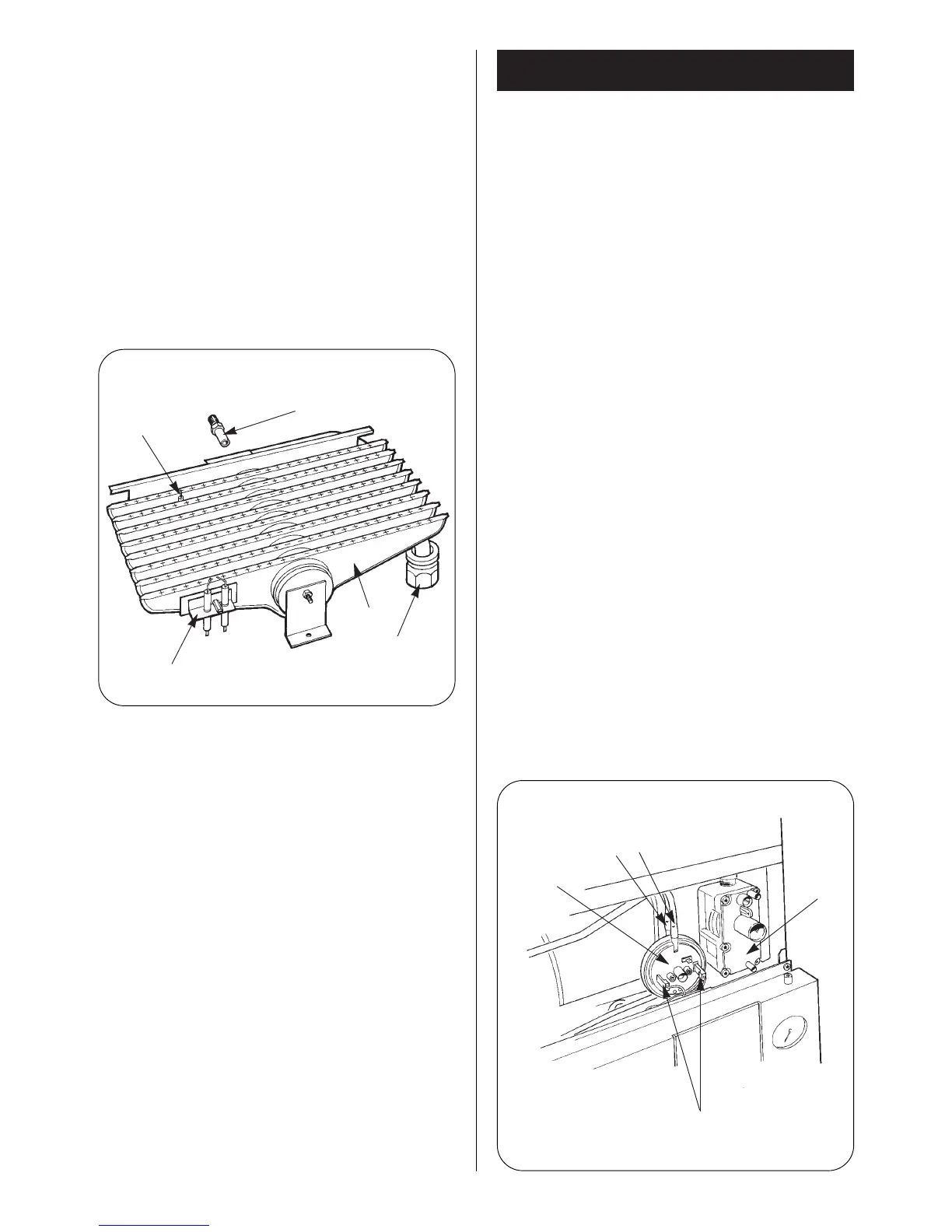
Fig. 29. Burner and electrode.
Flame sensor
Spark electrode
assembly
Burner fixing nut
Burner
Burner injector
Fig. 30. Air pressure switch.
Air pressure
switch
Terminals 2 and 3
Gas valve
-
Red tube
+
 Loading...