Installation and commissioning
Comfort+ I RF/Stat RF – 6720886119 (2018/07)
6
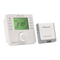
3.1.3 Installing Comfort+ I RF/Stat RF control unit
Fig. 5 Installation location of the control unit
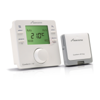
Fig. 6 Wireless range
Releasing control unit from wall socket
Fig. 7 Releasing control unit from wall socket
Wall-mounted installation
Find a position with good signal strength before starting the
wall-mounted installation of the control unit.
If the signal strength is low, check out another position in the
room, until the best possible signal strength is achieved
( page 7).
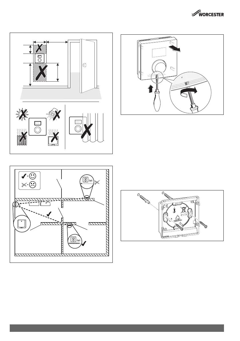
▶ Use the wall socket as a template to mark the position of the
screws.
▶ Drill two suitable holes for the length and diameter of the
rawl plugs.
Fig. 8 Installing the wall socket for the control unit
▶ Insert the rawl plugs.
▶ Insert the screws in such a way, that they protrude
sufficiently to enable the wall socket to fit behind the screw
heads.
▶ Install the wall socket horizontally.
°C
°F
750
≥ 1000
≥ 1200
750
600
°C
°F
500
0010021101-001
°C
°F
°C
°F
°C
°F
0010021103-002
1.
3.
0 010 020 505-001
2.
6720810965-08.1Wo
 Loading...