EasyManua.ls Logo

Yaesu FT-767GX Service Manual

Yaesu FT-767GX
152 pages
To Next Page IconTo Next Page
To Previous Page IconTo Previous Page
Page #52 background imageLoading...
Page #52 background image

Table of Contents

Other manuals for Yaesu FT-767GX

Question and Answer IconNeed help?

Do you have a question about the Yaesu FT-767GX and is the answer not in the manual?

Yaesu FT-767GX Specifications

General IconGeneral
TypeHF/VHF/UHF Transceiver
ModeSSB, CW, AM, FM
IF Rejection70 dB
Voltage13.8 V DC
Selectivity6 kHz (AM)
Image Rejection70 dB
Frequency Range50-54 MHz, 144-148 MHz, 430-450 MHz
Power Output100W (HF), 50W (VHF)

Summary

Service and Alignment Overview

Cover Removal Procedures

External Component and Panel Removal

Steps for removing external panels and securing components.

Internal Connection Handling

Locating and disconnecting internal connectors.

Chassis Separation Process

Procedures for separating the main chassis halves.

Alignment Equipment Requirements

Power Supply Unit (PSU) Checks

24V Supply Verification

Connect DC voltmeter to J9002, adjust VR6003.

13.5V Supply Verification

Connect voltmeter to J9007, adjust VR6004.

Board Component Locations

Local Unit Alignment Procedures

General Alignment Setup

Make all measurements and adjustments in CW mode.

Oscillator and Frequency Adjustments

Adjust local oscillators, TCXO, VCOs, and frequencies.

Bandpass Filter Alignment

Tune and adjust various bandpass filters.

Main Loop VCOs Calibration

Set display to 3.999.99, adjust transformer.

2nd Local Level Check

Connect voltmeter to J3001, adjust T3009 and T3011.

SSB Carrier Point Check (Transmit)

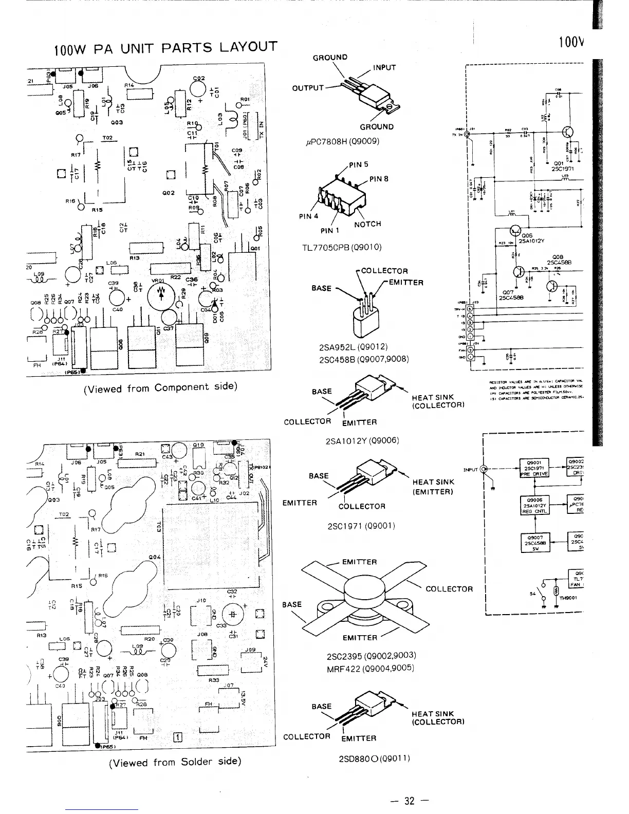
Connect dummy load, adjust VR901 for 250 mA.

IF Unit Alignment Procedures

Oscillator and Frequency Calibration

Adjust oscillator frequencies and filters for receive/transmit.

Receiver IF and Gain Adjustments

Align receiver IF, adjust IF gain and FM sensitivity.

Meter and Squelch Calibration

Calibrate S-meter, discriminator, squelch, and noise blanker.

IF Notch Resonance Adjustment

Tune to 14.2 MHz, adjust VR1011 and VR1007.

Tone Squelch Threshold Calibration

Set SQL control, adjust VR1019.

RF Unit Transmitter Alignment

ALC, Metering, and Voltage Calibration

Adjust ALC levels, meters, and check voltage readings.

Transmitter Alignment Procedures

Align IF transformers, power, SWR, and carrier balance.

AM Carrier and Speech Processor Alignment

Adjust AM carrier levels and speech processor settings.

FM Modulator Deviation Adjustment

Tune to 14.2 MHz, adjust VR1016 and VR1015.

IF Monitor Adjustments (AM)

Tune to 14.2 MHz, adjust T1016 and D1060.

PA Unit Idling Current Check

Antenna Tuner Unit Alignment

Variable Capacitor Adjustment

Preset VR5003 and VR5004, adjust by hand.

Tuner Stop SWR Threshold Adjustment

Tune to 14.2 MHz, connect dummy load, adjust VR5001.

Tuner Auto-Start SWR Threshold Adjustment

Tune to 14.2 MHz, adjust VR5002.

FT-767GX Connection Diagram

FT-767GX Block Diagram (AM Mode)

FT-767GX Block Diagram (CW Mode)

FT-767GX Block Diagram (SSB Mode)

FT-767GX Block Diagram (FM Mode)

Related product manuals