CS2X
7
2. DM Circuit Board
2-1 Remove the bottom assembly (See Procedure 1.)
2-2 Remove the two (2) screws marked [80], and the
screw marked [100A]. The DM circuit board with the
shield box can then be removed. (Fig. 2)
2-3 Remove the seven (7) screws marked [100] and the
four (4) screws marked [110B]. The DM circuit board
can then be removed from the shield box. (Fig. 3)
2-4 Pull off the power switch knob from the DM circuit board.
The lithium battery is not a part of the DM circuit
board. When you replace the DM circuit board, you
should remove the lithium battery from the board,
and put it back into the holder on the new circuit
board. (Fig. 4)
You can remove the lithium battery by pushing the
hook of the battery holder. (Fig. 4)
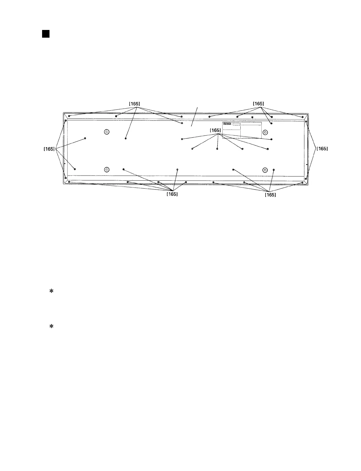
[165]: Bonding Tapping Screw-B 4.0X10 MFZN2BL (VJ254100)
DISASSEMBLY PROCEDURE
Fig.1
Bottom assembly
1. Bottom Assembly
1-1 Remove the thirty-three (33) screws marked [165].
The bottom assembly can then be removed. (Fig. 1)
3. Keyboard Assembly
3-1 Remove the bottom assembly. (See Procedure 1.)
3-2 Remove the DM circuit board with the shield box.
(See Procedure 2-2.)
3-3 Remove the four (4) screws marked [60A]. The
keyboard assembly and the two (2) MKR angles can
then be removed. (Fig. 2)
3-4 Removed the ten (10) screws marked [40]. The
keyboard assembly can then be removed from the
five (5) MKF angles. (Fig. 2)
 Loading...