8 Rear panel
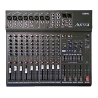
MX12/4—Owner’s Manual
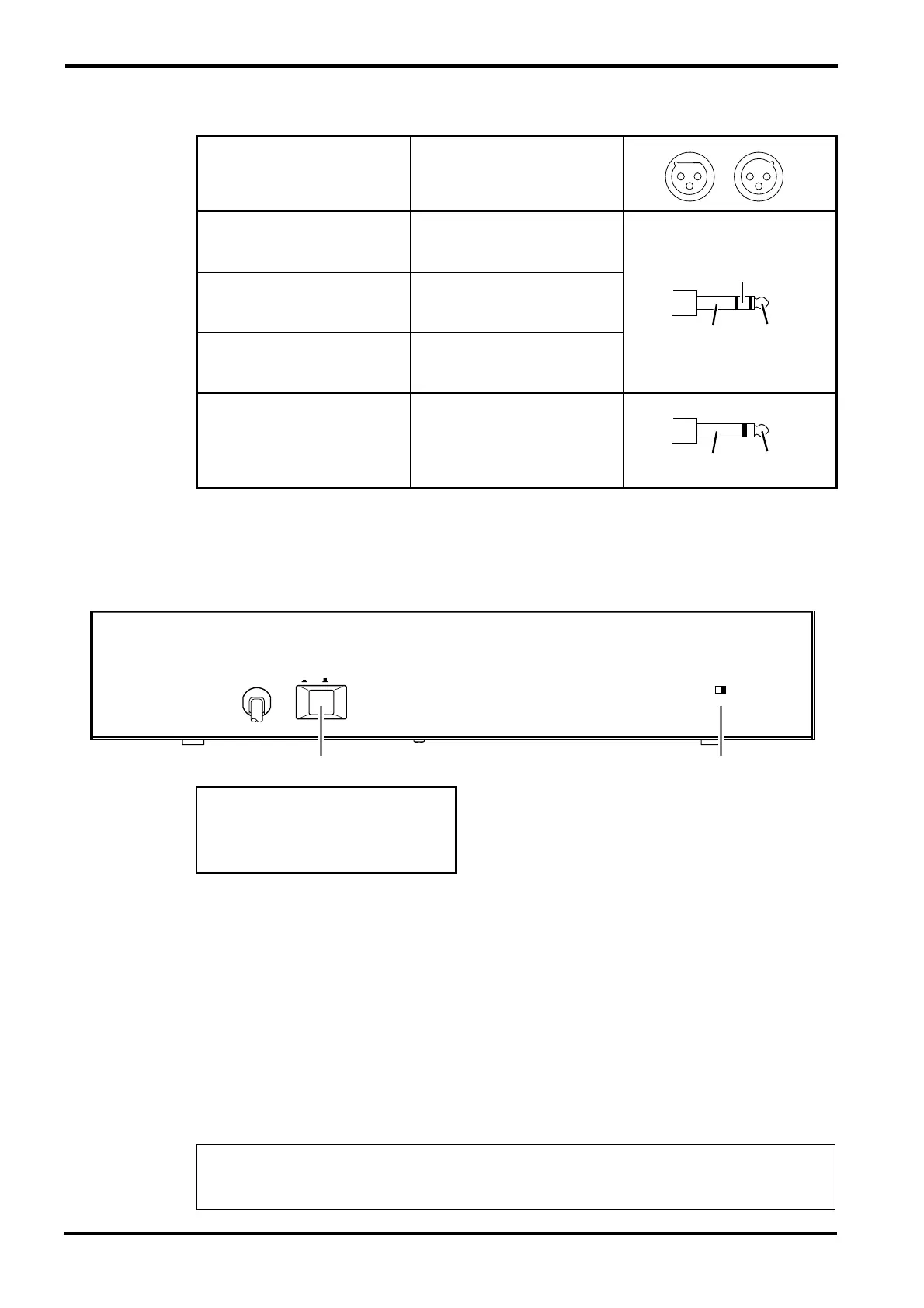
Connector polarity
Rear panel
1 POWER switch
When this is on, power is applied to the unit.
When turning off the power, the rule for audio equipment is to turn off devices in the order of
their closeness to the speakers (normally beginning with the power amp).
2 PHANTOM switch
This switch turns the phantom power on/off for all channels 1~8.
Use this when you are using condenser microphones.
When this switch is on, +48V DC will be supplied to pins 2 and 3 of all XLR type MIC INPUT
connectors.
If you do not require phantom power, be sure to set this in the OFF position.
MIC INPUT
ST OUTPUT
Pin 1: ground
Pin 2: hot (+)
Pin 3: cold (–)
LINE Input
Tip: hot (+)
Ring: cold (–)
Sleeve: ground
INS I/O
Tip: Output
Ring: Input
Sleeve: ground
C-R OUT
Tip: L
Ring: R
Sleeve: ground
Stereo Input
RTN
GROUP OUTPUT
SEND MONI1
SEND EFFECT/MONI2
Tip: hot
Sleeve: ground
Note: Although it will not cause problems to connect balanced dynamic microphones or line
level devices with this switch turned on, connecting unbalanced devices or devices for which
the center of the transformer is ungrounded may cause hum or malfunction.
PHANTOM MASTER
CH1 ~ 8
ON OFF
(+48V)
POWER
ON ⁄ OFF
21
Phantom Power Warning
To prevent hazard or damage, connect
only microphones and cables that
conform to the IEC268-15A standard.
 Loading...