EasyManuals Logo

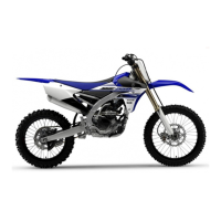
Yamaha YZ250F User Manual

Yamaha YZ250F
356 pages
To Next Page IconTo Next Page
To Previous Page IconTo Previous Page
Page #215 background imageLoading...
Page #215 background image
VALVES AND VALVE SPRINGS
5-22
EAS1SM5220
VALVES AND VALVE SPRINGS
Removing the valves and valve springs
Order Part name Q’ty Remarks
Cylinder head
Refer to “CYLINDER HEAD” on page 5-18.
1
Valve lifter
4
2
Adjusting pad
4
3
Valve cotter
8
4
Valve spring retainer
4
5
Valve spring
4
6
Valve stem seal
4
7
Valve spring seat
4
8
Intake valve
2
9
Exhaust valve
2
For installation, reverse the removal proce-
dure.

Table of Contents

Questions and Answers:

Question and Answer IconNeed help?

Do you have a question about the Yamaha YZ250F and is the answer not in the manual?

Yamaha YZ250F Specifications

General IconGeneral
Displacement250cc
Bore x Stroke77.0 mm x 53.6 mm
Final DriveChain
Suspension / RearKYB® single shock; fully adjustable, 12.5-in travel
Brakes / FrontHydraulic single disc brake, 270mm
Brakes / RearHydraulic single disc brake, 240mm
Fuel Capacity1.6 gal
Engine TypeLiquid-cooled, DOHC, 4-stroke
Fuel DeliveryFuel injection
IgnitionTCI
Transmission5-speed; multiplate wet clutch
Suspension / FrontKYB® Speed-Sensitive System inverted fork; fully adjustable, 12.2-in travel
Tires / Front80/100-21

Related product manuals