20 21
DESCRIPTION OF PRODUCT
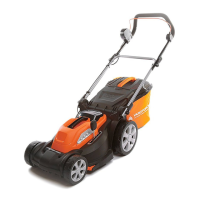
Parts description (Fig. A)
1. Upper handle
2. Switch box
3. Cable clip
4. Grass bag
5. Roller
6. Cutting height adjustment lever
7. Carry handle
8. Battery pack locating tank
9. Rotating knob
10. Switch lever
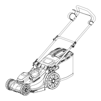
Check the delivery parts (Fig. B)
Remove the machine from its packaging carefully and make sure that all of the following parts
are present:
A. Lawnmower with upper handle
B. Lower brace
C. Grass bag
D. Rotating knob x2
E. Installation screw x2
F. Cable clip x2
G. Manual
H. Battery pack
I. Charger
WARNING: If any parts are damaged or missing, do not operate this tool until these
parts have been replaced. Failure to heed this warning could result in serious
personal injury.
NOTE: Always recycle the packaging in accordance with local recycling guidelines.
INSTALLATION
Assemble the lower brace (Fig. C)
1. Attach the lower brace to the deck.
2. Use two installation screws to x the lower brace.
Attach the top handle to lower brace (Fig. D)
Mount the top handle to the lower brace by using the two rotating knobs.
Fitting the cable clip (Fig. E)
Ensure that the cable clips supplied are used to x the cable to the lower brace.
Attach the grass bag
Attach the grass bag to the frame by xing the plastic hooks onto the side (Fig. F)
Lift the safety ap with one hand and hook in the grass bag. Release the ejector ap to
secure the grass bag in position. (Fig. G)

 Loading...