62 YASKAWA ELECTRIC TOBP C720600 01E YASKAWA AC Drive Option CDBR-D, LKEB- Installation Manual
9 CDBR Braking Unit and LKEB Braking Resistor Selection
9 CDBR Braking Unit and LKEB Braking Resistor Selection
◆ CDBR Braking Unit and LKEB Braking Resistor Selection
Select a CDBR Braking Unit and LKEB Braking Resistor Unit based on application-specific
requirements and the selected AC drive.
Refer to the local catalog for selections based on other drive models.
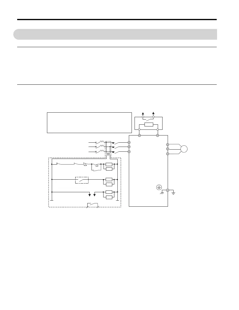
◆ CDBR Braking Unit Fault Circuit Connection Diagrams
Figure 28
Figure 28 Fault Circuit Connection Diagram A (LKEB Braking Resistor Unit)
<1> 200 V class drives do not require a control circuit transformer.
<2> Set L3-04 to 0 or 3 to disable Stall Prevention during deceleration when using an LKEB Braking Resistor Unit.
Enabling the function under these conditions may prevent the drive from stopping within the specified
deceleration time.
LKEB Braking
Resistor Unit
Braking resistor
overheat switch
(thermal relay trip)
Fault relay contact
(Ground)
Drive
Braking resistor
overheat switch
(thermal relay trip)
Wiring sequence should shut off power to the drive
when a CDBR transistor short-circuit detection
output is triggered or a braking resistor unit
overheat switch is triggered.
ELCB (MCCB)
R
S
T
M
12
PB
R/L1
MC
S/L2
T/L3
B1
B2
U/T1
V/T2
W/T3
SA
12
TRX
MC
MA
TRX
SA
ON
OFF
THRX
MC
MC
SA
THRX
MC MB
<2>
<1>
3-phase
TOBP_C720600_01E_9_0_E.book 62 ページ 2017年8月25日 金曜日 午後2時8分
 Loading...


