IM 01E21A03-01EN
7
<2. Explosion Protection Type>
7
2.2 Cable Entry
The type of cable entry is stamped near the cable
entry port according to the following codes.
Marking Screw Size
N ASME 1/2 NPT Female
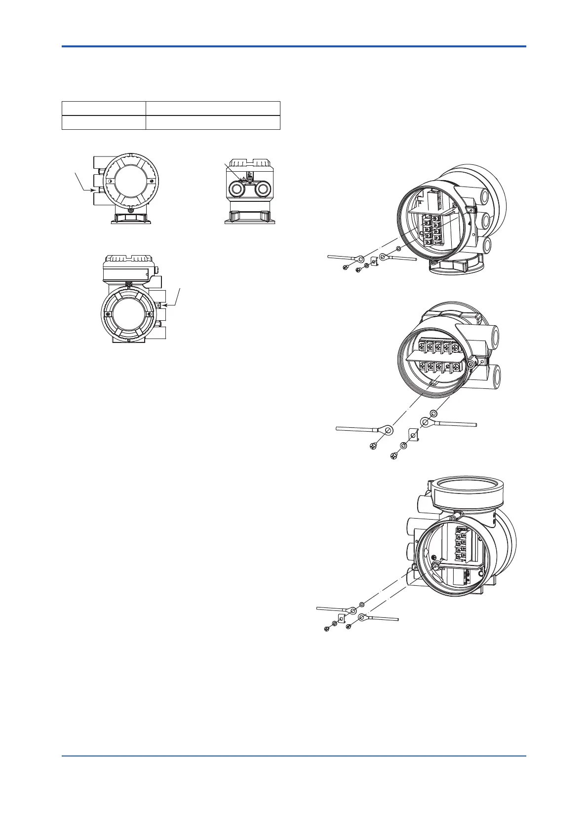
(1) Integral Flowmeter (2) Remote Sensor
(3) Remote Transmitter
2.3 Installation
• All wiring shall comply with NFPA70 (US) and
local electric codes and requirements.
• Unused apertures shall be closed with suitable
certied blanking elements.
(The plug attached is certied.)
• The sensor is not surrounded by pipe insulation
material.
• In hazardous location, wiring shall be in conduit as
follows.
“SEAL ALL CONDUITS WITHIN 18 INCHES”
• In order to prevent the grounding conductor from
loosening, the conductor must be secured to the
terminal, tightening the screw with appropriate
torque. Care must be taken not to twist the conductor.
• Warning: In cases where the ambient temperature
exceeds 50°C, use external heat resistant wiring with
a maximum allowable temperature of 70°C or above.
• For IS Output type, refer to DIE016-A92 (Control
Drawin
g)
The grounding terminals are located on the inside
and outside of the terminal area.
Connect the cable to the grounding terminal in
accordance with wiring procedure (a) or (b).
(a) Internal grounding terminal
(b) External grounding terminal
(1) Integral Flowmeter
(a)
(b)
(2) Remote Sensor
(a)
(b)
(3) Remote Transmitter
(b)
(a)
 Loading...
