App-1
IM WT310E-02EN
Appendix
App
Appendix 1 How to Make Accurate Measurements
Effects of Power Loss
By wiring a circuit to match the load, you can minimize the effects of power loss on measurement
accuracy. We will discuss the wiring of the DC power supply (SOURCE) and a load resistance (LOAD)
below.
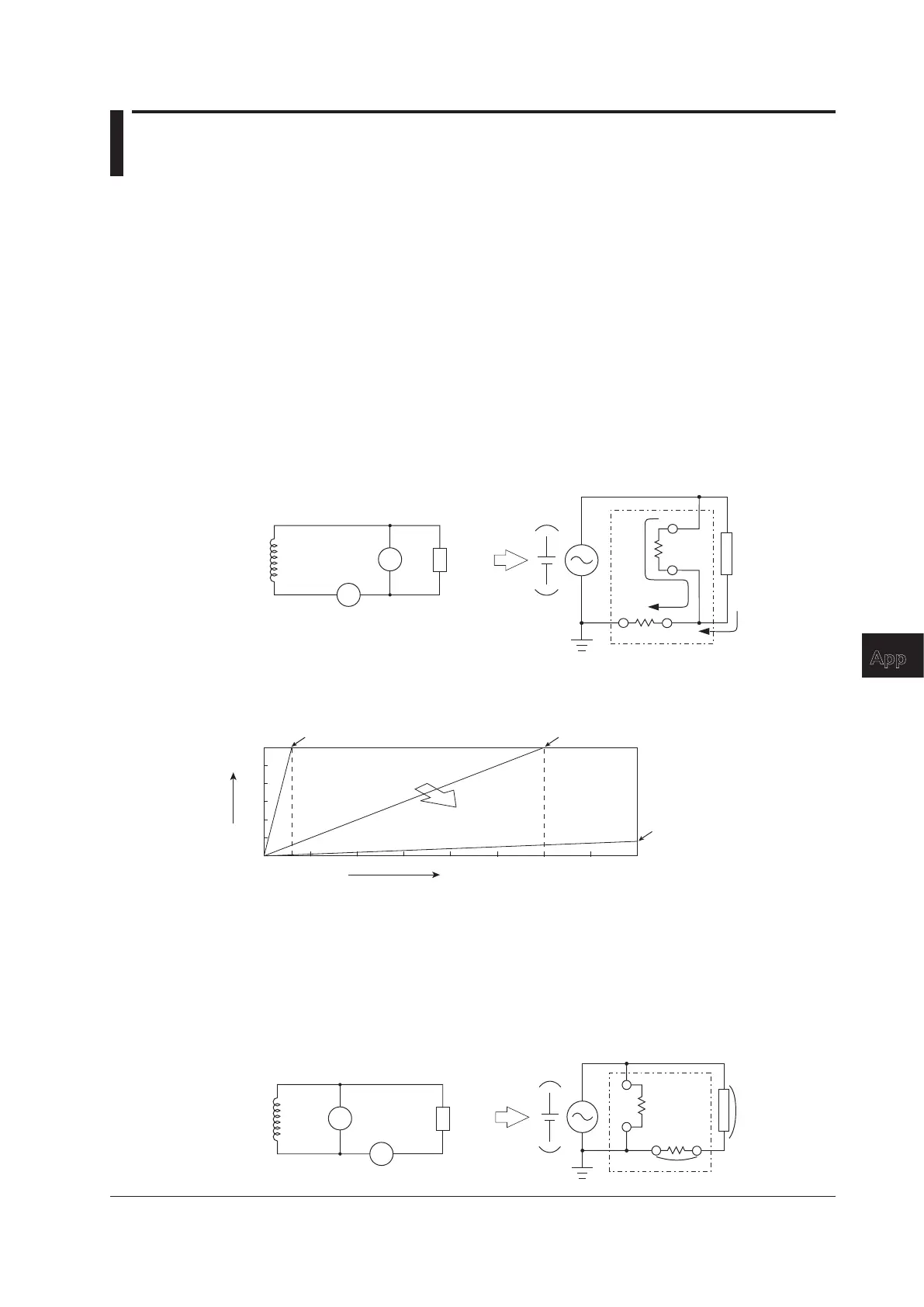
When the Measured Current Is Relatively Large
Connect the voltage measurement circuit between the current measurement circuit and the load. The
current measurement circuit measures the sum of i
L
and i
V
. i
L
is the current flowing through the load of
the circuit under measurement, and i
V
is the current flowing through the voltage measurement circuit.
Because the current flowing through the circuit under measurement is i
L
, only i
V
reduces measurement
accuracy. The input resistance of the voltage measurement circuit of this instrument is approximately
2MΩ.Iftheinputvoltageis600V,i
V
isapproximately0.3mA(600V/2MΩ).Iftheloadcurrenti
L
is 3 A
ormore(theloadresistanceis200Ωorless),theeffectofi
V
on the measurement accuracy is 0.01%
or less. If the input voltage is 100 V and the current is 5 A, i
V
=0.05mA(100V/2MΩ),sotheeffectof
i
V
on the measurement accuracy is 0.001% (0.05 mA/5 A).
SOURCE
LOAD
This instrument
V
C
i
V
i
L
LOAD
SOURCE
U
I
C
V
±
±
±
±
As a reference, the relationships between the voltages and currents that produce effects of 0.01%,
0.001%, and 0.0001% are shown in the figure below.
600
400
200
0
Measured current (A)
Measured voltage (V)
0.01% effect
0 5 10 15 20 25 30 35 40
0.0001% effect
Smaller effect
3
When the Measured Current Is Relatively Small
Connect the current measurement circuit between the voltage measurement circuit and the load. In
this case, the voltage measurement circuit measures the sum of e
L
and e
I
. e
L
is the load voltage, and
e
I
is the voltage drop across the current measurement circuit. Only e
I
reduces measurement accuracy.
For example, the input resistance of the current measurement circuit of the WT332E/WT333E is
approximately6mΩ.Iftheloadresistanceis600Ω,theeffectonthemeasurementaccuracyis
approximately0.001%(6mΩ/600Ω).FortheinputresistancesoftheWT310EandWT310EH,see
chapter 7.
SOURCE
LOAD
V
C
This instrument
e
L
e
I
SOURCE
LOAD
U
I
C
V
±
±
±
±
Appendix

 Loading...


