280241-YIM-D-0909
Johnson Controls Unitary Products 5
INSTALLATION
LIMITATIONS
These units must be installed in accordance with the follow-
ing national and local safety codes.
1. National Electrical Code ANSI/NFPS No. 70 or Canadian
Electrical Code Part 1, C22.1 (latest editions).
2. National Fuel Gas Code Z223.1 or CSA B149.1 Installa-
tion Code.
3. Local gas utility requirements.
4. Local plumbing and waste water codes and other appli-
cable local codes.
Refer to Table 1 for unit application data and to Tables 3 thru
6 for gas heat application data.
If components are to be added to a unit to meet local codes,
they are to be installed at the dealer's and/or the customer's
expense.
Size of unit for proposed installation should be based on heat
loss/heat gain calculations made in accordance with industry
recognized procedures identified by the Air Conditioning
Contractors of America.
LOCATION
Use the following guidelines to select a suitable location for
these units.
1. Unit is designed for outdoor installation only.
2. Condenser must have an unlimited supply of air. Where
a choice of location is possible, position unit on either
north or east side of building.
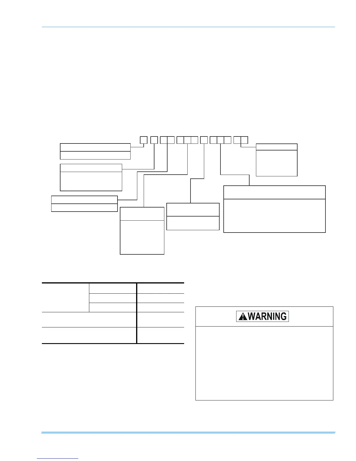
FIGURE 1 - PRODUCT NOMENCLATURE
D 1 N P N
PRODUCT CATEGORY
3
0 6 0 630 6
VOLTAGE CODE
06 = 208/230-1-60
25 = 208/230-3-60
46 = 460-3-60
024 = 24,000 BTUH
042 = 42,000 BTUH
030 = 30,000 BTUH
048 = 48,000 BTUH
060 = 60,000 BTUH
036 = 36,000 BTUH
58 = 575-3-60
D = Single Package Air Conditioner
PRODUCT IDENTIFIER
NP = 13 SEER Gas Heat/Electric
NOMINAL COOLING
CAPACITY (MBH)
N = Single Stage
D = Two Stage
FACTORY INSTALLED
NATURAL GAS HEAT
036 = 36,000 BTUH
056 = 56,000 BTUH (36,400 BTUH)
065 = 65,000 BTUH
072 = 72,000 BTUH (46,800 BTUH)
090 = 90,000 BTUH (56,160 BTUH)
110 = 110,000 BTUH (70,200 BTUH)
NOMINAL HIGH GAS HEAT OUTPUT CAPACITY
(NOMINAL LOW GAS HEAT OUTPUT CAPACITY)
PRODUCT GENERATION
1 = 1st Generation
2 = 2nd Generation
3 = 3rd Generation
TABLE 1: UNIT APPLICATION DATA
Voltage Variation
Min. / Max.
1
1. Rated in accordance with ARI Standard 110, utilization
range “A”.
208/230V
2
2. “T1” transformer primary tap must be moved from the
230 volt connection to the 208 volt connection for low
voltage applications of 208 volt and below
187 / 252
460V 432 / 504
575V 540 / 630
Wet Bulb Temperature (°F) of Air on
Evaporator Coil, Min. / Max.
57 / 72
Dry Bulb Temperature (°F) of Air on
Condenser Coil, Min.
3
/ Max.
3. A low ambient accessory is available for operation
down to 0 °F.
45 / 120
Excessive exposure of this furnace to contami-
nated combustion air may result in equipment
damage or personal injury. Typical contaminates
include: permanent wave solution, chlorinated
washes and cleaners, chlorine based swimming
pool chemicals, water softening chemicals, carbon
tetrachloride, halogen type refrigerants, cleaning
solvents (e.g. perchloroethylene), printing inks,
paint removers, varnishes, hydrochloric acid,
cements and glues, antistatic fabric softeners for
clothes dryers, masonry acid washing materials.

 Loading...