036-21573-001 Rev. A (0304)
2 Unitary Products Group
All dimensions are in inches. They are subject to change without
notice. Certified dimensions will be provided upon request.
Physical and Electrical Data
MODEL
AM012M1021 AM018M1021 AM024M1021 AM030M1021
Unit Supply Voltage 208-230V, 1φ, 60Hz
Normal Voltage Range
1
187 to 252
Minimum Circuit Ampacity 8.8 10.1 15.3 19.3
Max. Overcurrent Device Amps
2
15 15 20 25
Compressor Type Rotary Recip Recip Recip
Compressor Amps
Rated Load 6.7 7.7 11.5 14.7
Locked Rotor 33486073
Crankcase Heater No No No No
Fan Motor Amps Rated Load 0.5 0.5 0.9 0.9
Fan Diameter Inches 17-1/2 17-1/2 17-1/2 17-1/2
Fan Motor
Rated HP 1/12 1/12 1/8 1/8
Nominal RPM 1,100 1,100 1,075 1,075
Nominal CFM 1,600 1,550 1,750 1,750
Coil
Face Area Sq. Ft. 7.22 7.22 7.22 7.94
Rows Deep 1111
Fins / Inch 14 16 20 20
Liquid Line OD 3/8 3/8 3/8 3/8
Vapor Line OD 5/8 5/8 5/8 3/4
Unit Charge (Lbs. - Oz.)
3
3 - 2 3 - 1 3 - 4 3 - 9
Charge Per Foot, Oz. 0.66 0.66 0.66 0.68
Operating Weight Lbs. 94 114 119 122
1. Rated in accordance with ARI Standard 110, utilization range “A”.
2. Dual element fuses or HACR circuit breaker.
3. The Unit Charge is correct for the outdoor unit, matched indoor coil, and 15 feet of refrigerant tubing. For tubing lengths other
than 15 feet, add or subtract the amount of refrigerant, using the difference in length multiplied by the per foot value.
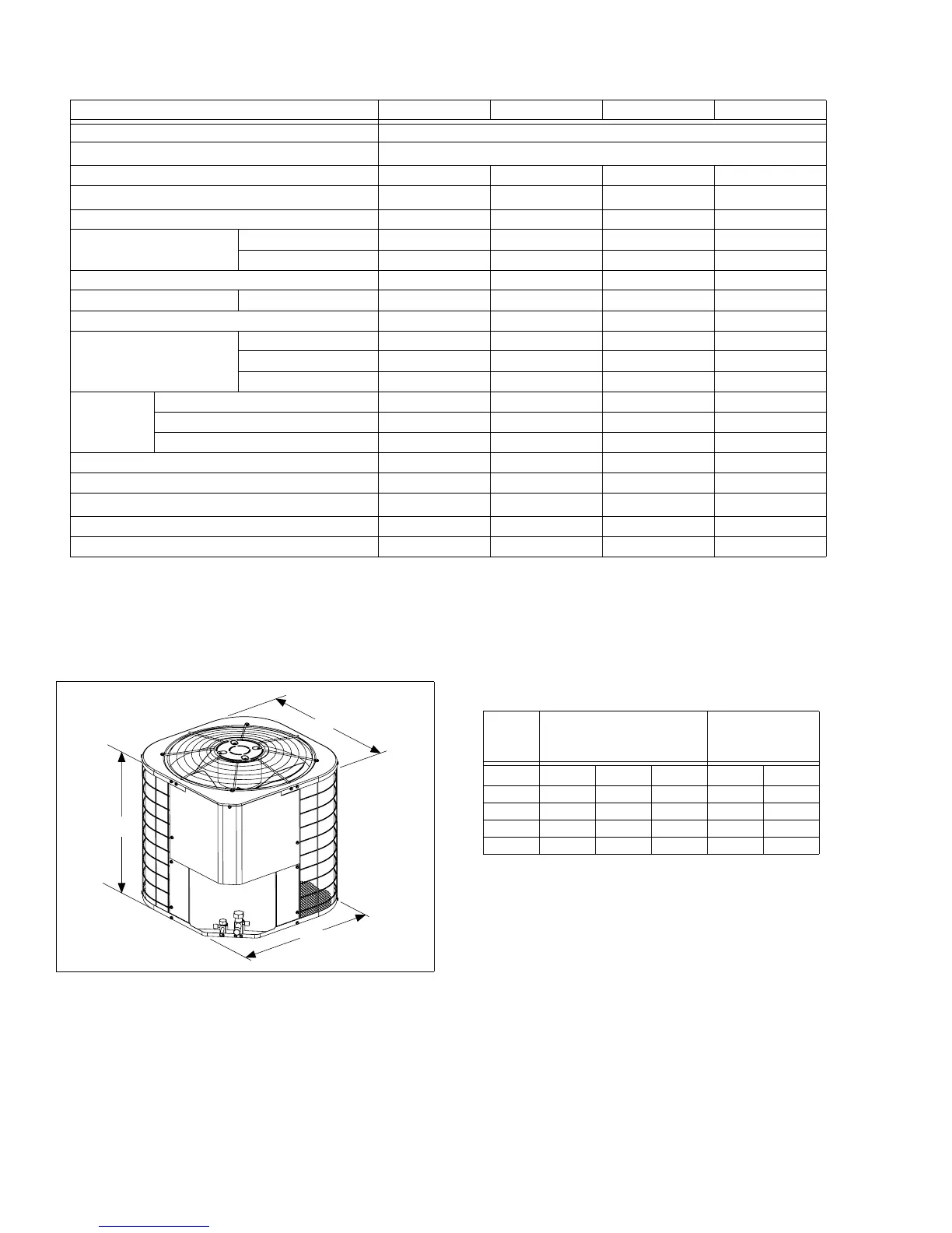
A
B
C
Unit
Model
Dimensions
(Inches)
Refrigerant
Connection
Line Size
A
1
1. Including Fan Guard
B C Liquid Vapor
012 22 21-3/4 21-3/4 3/8” 5/8”
018 22 21-3/4 21-3/4 3/8” 5/8”
024 22 21-3/4 21-3/4 3/8” 5/8”
030 24 21-3/4 21-3/4 3/8” 3/4”