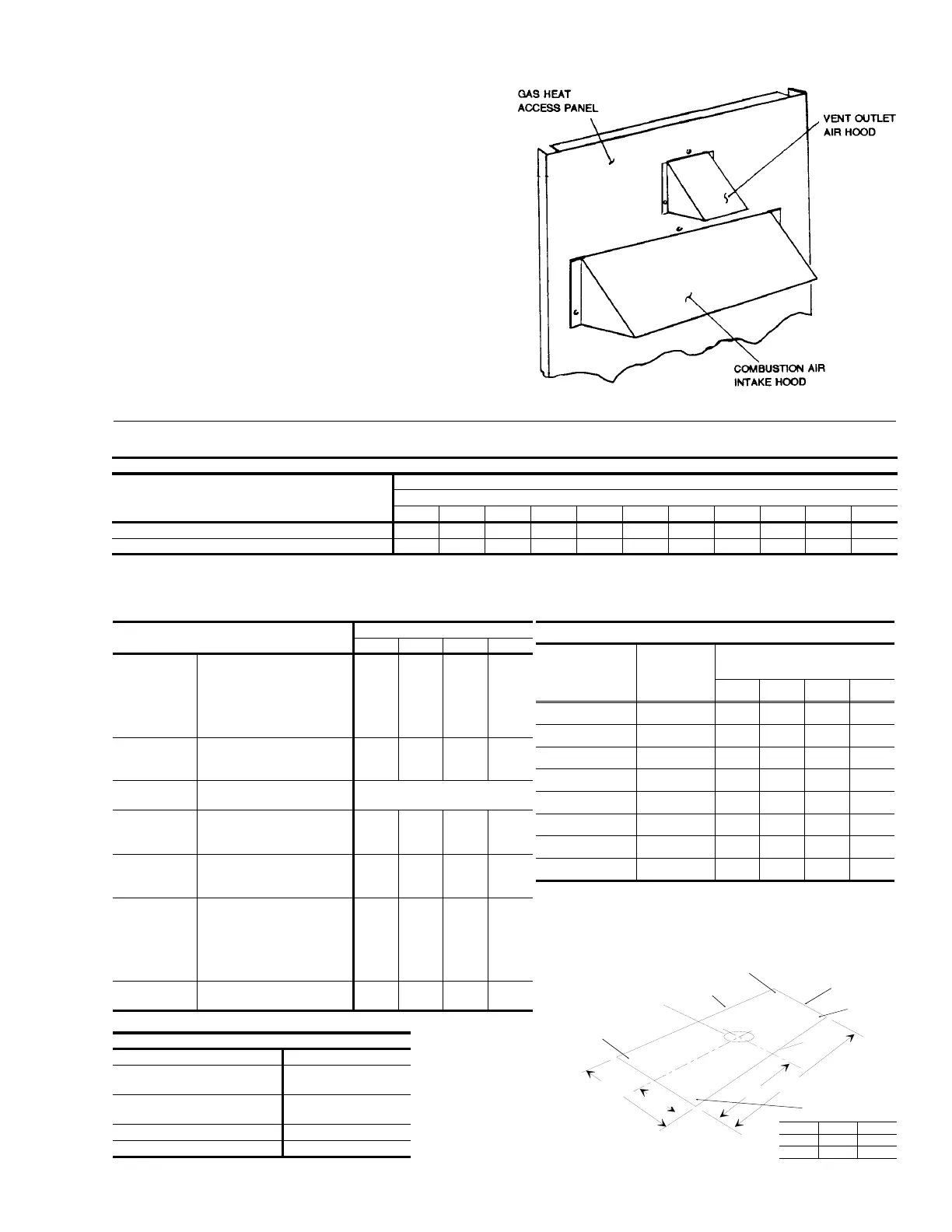
VENT AND COMBUSTION AIR HOODS
The vent and combustion air hoods are shipped attached to the
blower housing in the blower compartment. These hoods must
be installed on the outside of the gas heat access panel to
ensure proper unit function. The necessary mounting screws
are provided in a bag also attached to the blower housing.
The screen for the combustion air intake hood is secured to the
inside of the access panel opening with three fasteners and the
screws used for mounting the hood to the panel. The top flange
of this hood slips in under the top of the access panel opening
when installing. Refer to Figure 5. Remove the protective label
covering the opening just prior to installing this hood.
The vent hood (including its screen) is installed by inserting the
top flange of the hood into the slotted opening in the access
panel. The top screw secures the hood to the access panel.
The remaining two side screws must be installed after the
access panel is installed on the unit. These screws engage the
bottom flue box flange.
CAUTION: All three screws in the vent hood must be properly
installed before furnace operation to insure all com-
bustion products are exhausted from the unit.
FIG. 5
- VENT AND COMBUSTION AIR HOODS
EXTERNAL STATIC PRESSURE DROP
DESCRIPTION
RESISTANCE, IWG
CFM
1000 1200 1400 1600 1800 2000 2200 2400 2600 2800 3000
Economizer
1, 2
0.07 0.08 0.09 0.11 0.13 0.15 0.17 0.20 0.23 0.26 0.30
Bottom Duct Connections
1
0.06 0.07 0.08 0.09 0.10 0.11 0.12 0.14 0.16 0.19 0.22
1
Deduct these resistance values from the available external static pressure shown in the respective Blower Performance Table.
2
The pressure thru the economizer is greater for 100% outdoor air than for 100% return air. If the resistance of the return air duct system is less than 0.25 IWG, the unit will deliver less CFM
during full economizer operation.
TABLE 4
- STATIC RESISTANCES
FIG 6
- CENTER OF GRAVITY
APPROXIMATE
CENTER OF
GRAVITY
FRONT
48-11/32
21
32-1/8
15-1/4
82
1
⁄
4
“
X
44
7
⁄
8
“
CONDENSER
COIL END
BACK
CORNER C
CORNER D
CORNER B
CORNER A
Y
DIM. 3-5 TON 6 TON
Y 19-3/4" 22"
X 40-3/4" 44"
WEIGHTS
UNIT
SIZE
(heat)
UNIT
WEIGHT*
(lbs.)
CORNER WEIGHTS*
(location, lbs., see figure 6)
"A" "B" "C" "D"
036 (40 Mbh) 625 180 172 133 140
036 (79 Mbh) 635 180 177 138 140
048 (60 Mbh) 675 193 185 145 152
048 (99 Mbh) 685 193 190 150 152
060 (79 Mbh) 700 200 192 150 158
060 (99 Mbh) 710 200 197 155 158
072 (79 Mbh) 775 186 209 201 179
072 (99 Mbh) 785 186 214 206 179
* Weight = Unit + Economizer
MODELS
UNIT SIZE
036 048 060 072
EVAP.
BLOWER
CENTRIFUGAL BLOWER
(Dia. x Wd. in.)
FAN MOTOR HP
(Direct-Drive)
FAN MOTOR HP
(Belt-Drive)
12 x 10
1
⁄
2
1
1
⁄
2
12 x 10
3
⁄
4
1
1
⁄
2
12 x 10
1
1
1
⁄
2
12 x 11
1
1
1
⁄
2
EVAP.
COIL
ROWS DEEP
FINS PER INCH
FACE AREA (Sq. Ft.)
3
13
3.6
3
13
4.3
3
13
5.1
4
13
5.1
COMPR.
TYPE
HERMETICALLY SEALED SCROLL TYPE
COND.
FAN
PROPELLER DIA. (in.)
FAN MOTOR HP
NOM. CFM TOTAL
24
1
⁄
4
3,400
24
1
⁄
4
3,400
24
1
⁄
4
3,400
24
1
⁄
4
3,300
COND.
COIL
ROWS DEEP
FINS PER INCH
FACE AREA (Sq. Ft.)
1
16
17.1
1
16
17.1
1
22
17.1
2
16
16.7
AIR
FILTERS
(SEE NOTE)
QUANTITY PER UNIT
(15" x 20" x 1")
QUANTITY PER UNIT
(14" X 25" X 1")
TOTAL FACE AREA
(sq. ft.)
2
1
6.3
2
1
6.3
2
1
6.3
2
1
6.3
CHARGE
REFRIGERANT 22
(lbs./oz.)
5/8 6/8 6/8 10/0
NOTE: Filter racks are adapted for 1" or 2" thick filters.
TABLE 5
- PHYSICAL DATA
OPTIONS / ACCESSORIES WEIGHTS (lbs.)
Economizer 50
Motorized Outdoor
Air Damper
26
Barometric Relief/Fixed
Outdoor Air Intake Damper
10
Roof Mounting Curb 92
Belt-Drive Blower 5
530.18-N8W
Unitary Products Group 7
 Loading...