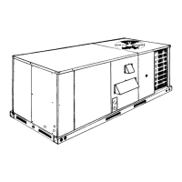
DISCONNECT SWITCH BRACKET FOR UNITS
WITH OPTIONAL BELT-DRIVE BLOWER
A special bracket for mounting a field-supplied disconnect
switch is provided in each unit ordered with an optional
belt-drive supply air blower. The bracket is shipped inside the
blower compartment taped to the top of the blower housing.
Install the bracket on the left hand side of the unit as shown in
Figure 7. Several existing screws at the top of the unit and one
screw approximately midway down from the top will be used
for mounting the bracket. Screws should be loosened only -
NOT REMOVED. Matching holes in the bracket have
elongated keyways allowing easy installation. Re-tighten
screws after bracket is in place to ensure panels will remain
leak tight.
GAS PIPING
Proper sizing of gas piping depends on the cubic feet per hour
of gas flow required, specific gravity of the gas and the length
of run. “National Fuel Gas Code” Z223-1992 (in the USA), or
the current Gas Installation Codes CAN/CGA-B149.1 and .2 (in
Canada) should be followed in all cases unless superseded by
local codes or gas company requirements. Refer to Table 3.
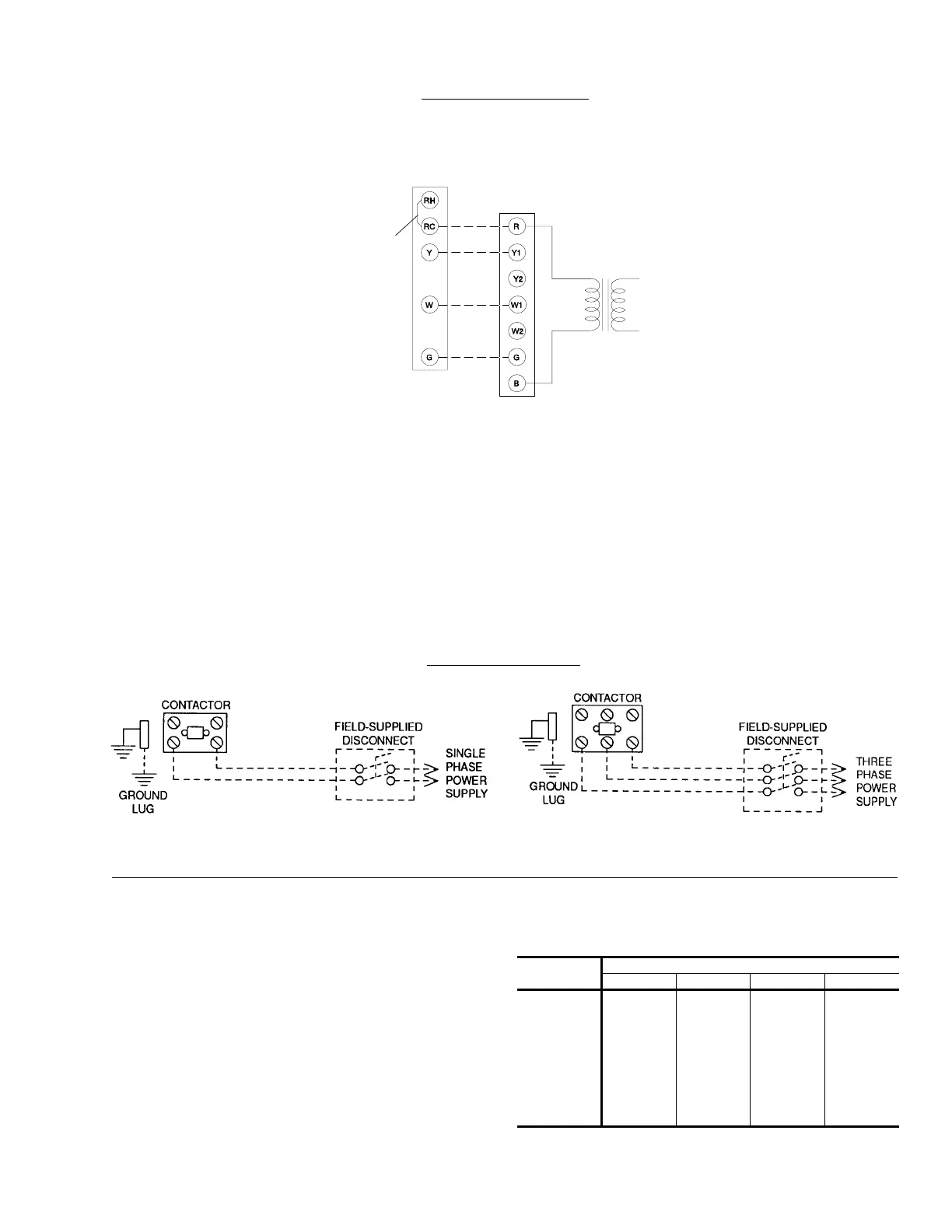
FIG. 2
- TYPICAL FIELD WIRING
REFER TO ELECTRICAL DATA
TABLES TO SIZE THE DISCONNECT
SWITCH, WIRING & OVERCURRENT
PROTECTION.
REFER TO ELECTRICAL DATA
TABLES TO SIZE THE DISCONNECT
SWITCH, WIRING & OVERCURRENT
PROTECTION.
TYPICAL POWER WIRING
TYPICAL CONTROL WIRING
Length in Feet
Nominal Iron Pipe Size
1/2 in. 3/4 in. 1 in. 1-1/4 in.
10
20
30
40
50
60
70
80
90
100
132
92
73
63
56
50
46
43
40
38
278
190
152
130
115
105
96
90
84
79
520
350
285
245
215
195
180
170
160
150
1,050
730
590
500
440
400
370
350
320
305
Maximum capacity of pipe in cubic feet of gas per hour. (Based upon a pressure drop of 0.3
inch water column and 0.6 specific gravity gas).
TABLE 3
- PIPE SIZING
THERMOSTAT
1
TERMINALS
UNIT TERMINAL
STRIP TB1
24 VOLT
TRANSFORMER
ADD
JUMPER
1
24 VOLT THERMOSTAT. IF THE UNIT HAS AN ECONOMIZER,
REMOVE JUMPER J1 FROM TERMINALS 8 AND 10 ON THE RELAY BOARD
TO PREVENT SIMULTANEOUS OPERATION OF THE SCROLL COMPRESSOR
AND THE ECONOMIZER. IF YOU WANT TO CONTROL THE ECONOMIZER ON A
SECOND STAGE OF COOLING OR HAVE AN ELECTRIC HEAT ACCESSORY
WITH TWO STAGES OF HEAT, USE THERMOSTAT.
COOLING / HEATING (24 VOLT THERMOSTAT)
CAUTION: Label all wires prior to disconnection when servic-
ing controls. Wiring errors can cause improper and
dangerous operation. Verify proper operation after
servicing.
530.18-N8W
Unitary Products Group 5
 Loading...