035-15241-003 Rev. A (201)
Unitary Products Group 19
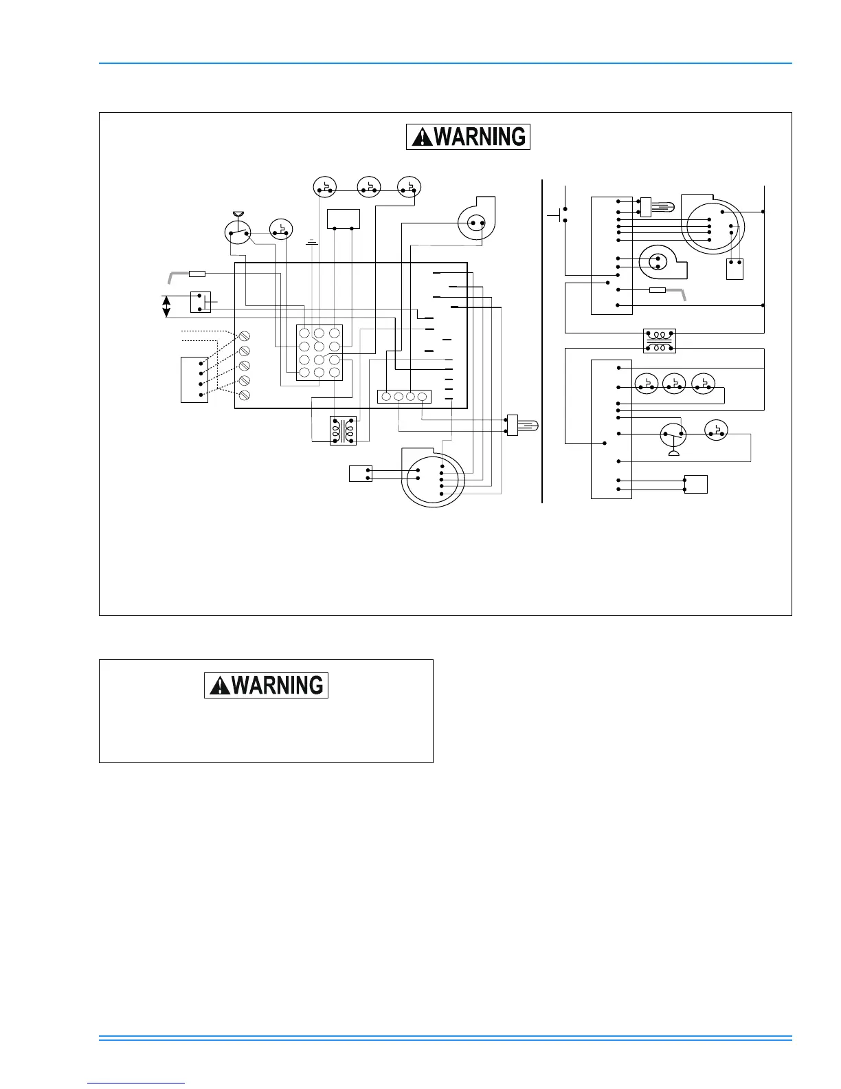
WIRING DIAGRAM
PRE-OPERATIONAL CHECKS
1. Be sure that the furnace is equipped for the type of gas
being supplied to the furnace. See unit rating plate. If LP
(propane) gas is to be used, make sure that the fur-
nace has been properly converted.
2. Manually spin circulating air blower wheel to ensure that
it turns freely and does not strike the blower housing.
3. Was the gas piping tested and/or purged of air then
checked for leaks? See instructions for gas piping. Even
the smallest leak must be eliminated before attempting
to light the furnace.
SEQUENCE OF OPERATION
These furnaces are equipped with an electric hot surface
burner ignition system. In response to a call for heat by the
room thermostat, a hot glowing ignitor lights the burners at
the beginning of each operation cycle. The burners will con-
tinue to operate until the thermostat is satisfied at which time
all burner flame is extinguished. During the off cycle no gas is
consumed. With the room thermostat set below room temper-
ature and with the electrical power and gas supply to the fur-
nace on, the normal sequence of operation is as follows:
1. When the room temperature falls below the setting of the
room thermostat, the thermostat energizes the furnace
control board.
2. When the furnace control board is activated, the vent
blower is turned on. A circuit is also made through the
normally open pressure switch contacts.
3. As the vent blower increases in speed, the contacts of
the pressure switch will close and complete the electrical
circuit to the ignitor.
4. During the next 30 seconds, the vent blower will bring
fresh air into the heat exchanger and the ignitor will
begin to glow. At the end of this period, the gas valve will
open and the burners will light.
5. After the burners light, a separate sensor acts as a flame
probe to check for the presence of flame. As long as a
flame is present, the system will monitor it and hold the
gas valve open.
DISCONNECT THE ELECTRIC POWER BEFORE SERVICING.
BDSS
ROS
LS
PS
T’STAT
= Blower Door Safety Switch
= Rollout Switch
= Limit Switch
= Pressure Switch
= Wall thermostat
XFMR
IGN
CAP
VM
GV
FS
= Transformer
= Hot Surface Ignitor
= Capacitor
= Vent Motor
= Gas Valve
= Flame Sensor
PS
FS
LS
ROS
VM
IGN
BLOWER
BLOWER
T’STAT
TO
A/C
BDSS
CAP
115V
XFMR
ROS ROS ROS
PS
LS
GV
CAP
COM
HI
MH
ML
LO
BRN
BRN
XFMR
115V
COM
HI
MH
ML
LO
VM
FS
24V
P-2B
P-4B
P-1B
P-3B
L1
XFMR
P-2A
NEU
IGN
P-6A
P-5A
P-11A
P-8A
P-7A
P-10A
P-3A
P-1A
P-9A
P-12A
HUM
EAC
XFMR
L1
PARK
PARK
HEAT
COOL
B
10
1
2
3
4
5
6
7
8
9
11
12
BLK
WHT
BLK
YEL
RED RED
ROS
ROS
GV
PUR
PUR
Y
W
R
G
Y
W
R
G
C
1
2
3
BLU
BLU
A
ORG
ORG
GRN
GRY
24V
115V
BLK
WHT
RED
YEL
BLU
RED
RED
BRN
BRN
RED
PUR
PUR
4
COOL
PARK
PARK
HEAT
NEUTRALS
Factory internal wiring shown solid. If any of the original
wire supplied with this unit must be replaced, it must be
replaced with Type 105º C thermoplastic or its equivalent.
SHOCK HAZARD - Be sure electrical power to
furnace is turned off before performing the pre-
operational checks.
 Loading...