258919-UIM-B-0107
2
INSPECTION
INSPECTIONINSPECTION
INSPECTION
As soon as a coil is received, it should be inspected for possible dam-
age during transit. If damage is evident, the extent of the damage
should be noted on the carrier’s delivery receipt. A separate request for
inspection by the carrier’s agent should be made in writing. See Local
Distributor for more information. Check drain pan for cracks or break-
age.
CLEARANCES
CLEARANCESCLEARANCES
CLEARANCES
During Installation
Clearance must be provided for:
1. Refrigerant piping and connections
2. Maintenance and servicing access - including cleaning the coil
3. Condensate drain line
4. Filter removal / change
5. Removal of coil assembly
LIMITATIONS
LIMITATIONSLIMITATIONS
LIMITATIONS
These coils should be installed in accordance with all national and local
safety codes. Check Tables 2, 3, and 4 for operating limitations.
SECTION III: COIL METERING DEVICES
SECTION III: COIL METERING DEVICESSECTION III: COIL METERING DEVICES
SECTION III: COIL METERING DEVICES
If the model number is of the following format: *****2A**, *****2B**
or *****2C** - The coil will have an R22 TXV metering device installed at
the factory.
If the model number is of the following model series:
*****3X** - The coil will require a TXV to be installed in the field. Refer to
installation manual with TXV kit. It is recommended to install the TXV kit
prior to installation of coil and brazing line sets.
TXV METERING DEVICE
TXV METERING DEVICETXV METERING DEVICE
TXV METERING DEVICE
Please refer to Tables 1-3 to verify proper and recommended line set
sizes and that this is a valid system match for the AC or HP unit
installed.
The temperature sensing bulb should be attached to the suction line
set. Refer to Figure 3.
NOTE: For models that have factory installed TXV’s, take caution not to
apply high temperatures to the TXV assembly or equalizer line while
brazing.
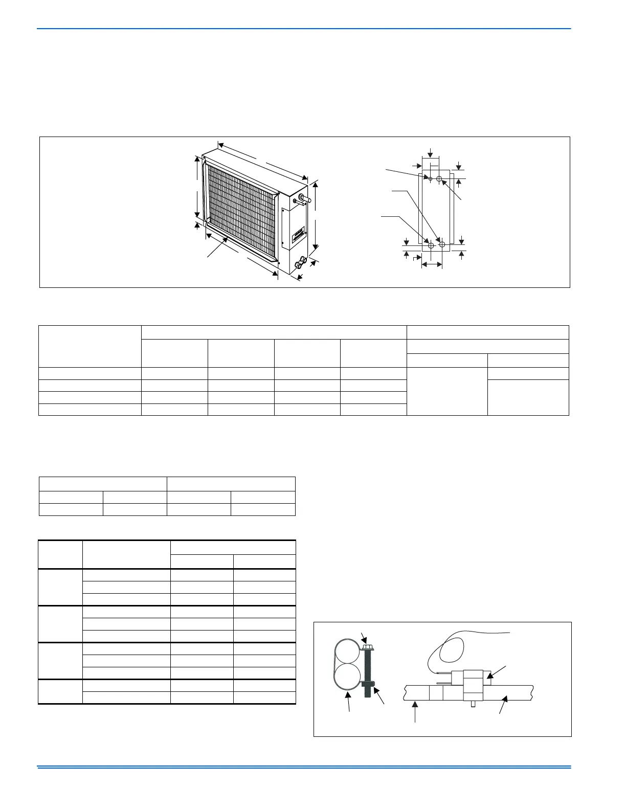
FIGURE 2: Coil - HD
1-3/4
C
5-5/8
B
A
D
3-3/4
2-5/8
1-3/8
VAPOR
CONN.
LIQUID
CONN.
3/4 NPT
SECONDARY
DRAIN CONN.
3/4 NPT
PRIMARY
DRAIN CONN.
7/8
1-7/8
4-1/8
1-3/8
OUTLET SAME
SIZE AS INLET
(3/4” FLANGE)
TABLE 1:
Dimensions
Model
Dimensions - Inches Refrigerant Connections
A B C D
Line Size
Liquid Vapor
HD24S**H1 28-3/4 24 23-3/4 21-5/8
3/8
3/4
HD36S**H1 28-3/4 28 23-3/4 25-5/8
7/8HD48S**H1 34-3/4 28 29-3/4 25-5/8
HD60S**H1 34-3/4 30 29-3/4 27-5/8
TABLE 2:
Entering Air Temperature Limits
WET BULB TEMP. (°F) DRY BULB TEMP. (°F)
MIN. MAX. MIN. MAX.
57 72 65 95
TABLE 3:
Coil Air Flow Limits
Coil
Size
Outdoor Unit
Tons
CFM Limits
Minimum Maximum
24
1 350 450
1-1/2 525 675
2 700 900
36
2 700 900
2-1/2 875 1125
3 1050 1250
48
3 1050 1250
3-1/2 1225 1575
4 1400 1750
60
4 1400 1750
5 1750 2200
FIGURE 3:
Proper Bulb Location
TXV BULB
(Cover completely
with insulation)
SCREW
CLAMP
NUT
SUCTION HEADER
SUCTION LINE
(FIELD INSTALLED)
 Loading...