heat pump CFM selections. Find the recommended system air-
flow in the table for the installed Air Handler model.
Moving up the table, identify the “COOL” tap jumper position (“A”,
“B”, “C” or No Jumper). Go to the connector board and set the
jumper horizontally for the “COOL” tap position. See Figure 8 for
the layout of the connector board.
NOTE: No jumper indicates the jumper should be removed or
placed in the “store” position (see Figure 8).
Return to Table 1 and move to the right to identify the “ADJ” tap
jumper position. Go to the connector board and set the jumper
horizontally for the “ADJ” tap position (refer to Figure 8). Again,
“No jumper” indicates the jumper should be removed or placed in
the “store” position.
To Set Heat Pump CFM:
The heat pump CFM setting is the same as the cooling CFM. No
additional CFM setting is required, however, you must remove the
jumper at the bottom of the connector board labeled “Remove for
Heat Pump” for heat pump operation. (See Figure 8.)
To Set Electric Heat CFM:
The blower speed required for the Electric Heat is different than
cooling. Refer to the label on the blower housing or Table 1 for the
possible CFM selections. Refer to Table 4 for the minimum
required CFM for the electric heater installed. Find the desired
airflow in Table 1. Moving up the table, identify the “HEAT” tap
jumper position. Go to the connector board and set the jumper
horizontally for the “HEAT” tap position.
CAUTION: DO NOT change the “ADJ” tap position on the con-
nector board as this will change your cooling CFM
previously selected.
To Set Delay Profile:
Every variable speed air handler has multiple “blower off delay”
profiles to optimize system performance and efficiency.
Refer to Table below for the type of system installed. set the
“DELAY” jumper tap position horizontally on the connector board
for the appropriate setting.
To Install Humidistat Accessory:
If the system is used with a humidistat accessory, connect the field
wires to screw terminals “R” and “BK” on the connector board.
See Figures 10 or 11.
IMPORTANT: Remove the jumper at the bottom of the connector
board marked “Remove for Humidistat” for humidistat operation.
MAINTENANCE
One permanent high velocity washable filter is provided with each
filter rack. This filter may be cleaned with a vacuum cleaner or
washed with warm water using a mild detergent. Do not use a
high velocity water stream. No coating is required. Install filter with
cloth mesh towards blower. Never turn a dirty filter to allow air flow
in the opposite direction.
Filters must be cleaned when they become dirty. Inspect at least
once per month. The frequency of cleaning depends upon the
hours of operation and the local atmospheric conditions. Clean
filters keep unit efficiency high.
COIL CLEANING
If the coil needs to be cleaned, it should be washed with Calgon
Coilclean (mix one part Coilclean to seven parts water). Allow
solution to remain on coil for 30 minutes before rinsing with clean
water. Solution should not be permitted to come in contact with
painted surfaces.
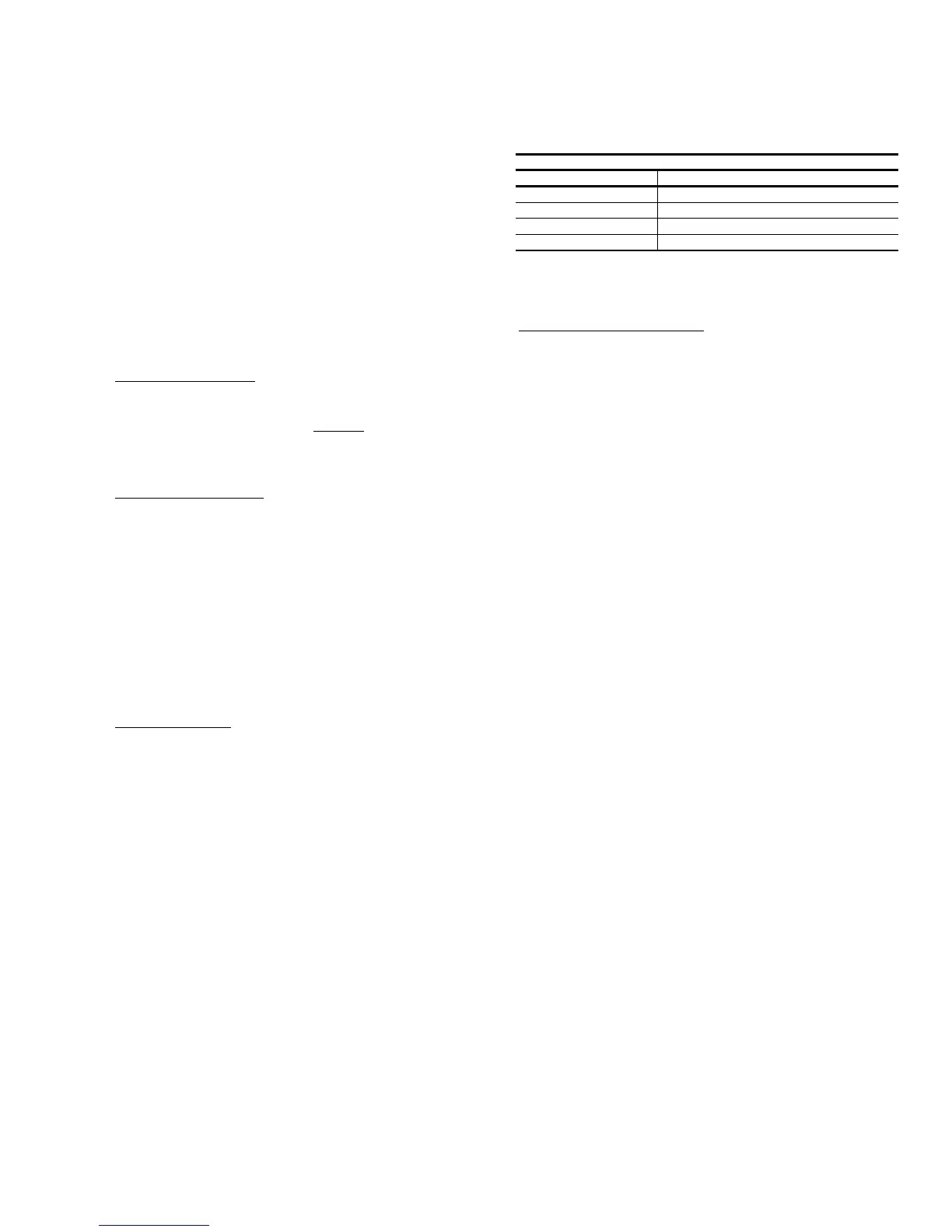
Delay Profile
“DELAY” Tap Unit Type
Jumper at “A” System wo/TXV or wo/ S.V.
Jumper at “B” System w/TXV or w/ S.V.
Jumper at “C” Two Stage Condensor
No Jumper Test Mode
TXV= Thermal Expansion Valve
SV= Solenoid Valve
535.03-N1Y
Unitary Products Group 7
 Loading...