5894307-UIM-B-0920
28 Johnson Controls Ducted Systems
Notes:
Airflow expressed in standard cubic feet per minute (SCFM).
Motor voltage at 115 V.
SECTION IX: SAFETY CONTROLS
CONTROL CIRCUIT FUSE
A 3-A fuse is provided on the control circuit board to protect the 24-V
transformer from overload caused by control circuit wiring errors. This is
an ATO 3, automotive type fuse and is located on the control board.
BLOWER DOOR SAFETY SWITCH
This unit is equipped with an electrical interlock switch mounted in the
burner compartment. This switch interrupts all power at the unit when
the panel covering the blower compartment is removed.
Electrical supply to this unit is dependent upon the panel that covers the
blower compartment being in place and correctly positioned.
AUXILIARY LIMIT SWITCH
These controls are mounted on the burner assembly. If the temperature
in the area surrounding burner exceeds its setpoint, the gas valve is de-
energized. The operation of this control indicates a malfunction in the
combustion air blower or heat exchanger or a blocked vent pipe con-
nection. Corrective action is required. These are manual reset controls
that must be reset before operation can continue.
PRESSURE SENSOR
This furnace is supplied with a pressure sensor, which monitors the flow
through the combustion air/vent piping and condensate drain system.
LIMIT CONTROLS
There is a high temperature limit control located on the furnace vesti-
bule panel near the gas valve. This is an automatic reset control that
provides over temperature protection due to reduced airflow. This may
be caused by the following:
• A dirty filter
• Indoor fan motor failure
• Too many supply or return registers closed or blocked off
The control module locks out if the limit trips five consecutive times. If
this occurs, the control resets and attempts ignition again after 1 h.
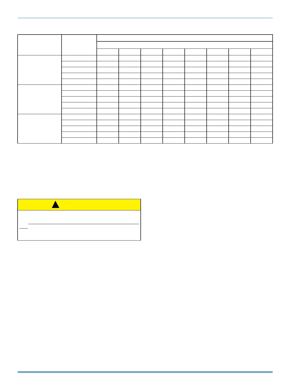
Table 15: Blower Performance CFM - Any Position (Without Filter)
Models Speed
Airflow Data (SCFM)
External Static Pressure (in. H
2
O)
0.1 0.2 0.3 0.4 0.5 0.6 0.7 0.8
TL9E060B12
High 1319 1287 1265 1232 1204 1171 1134 1098
Medium High 1128 1100 1073 1039 997 958 919 871
Medium 952 918 882 846 801 762 717 681
Medium Low 771 734 694 643 601 559 513 461
Low 710 675 632 584 540 491 445 397
TL9E080C16
High 1745 1711 1679 1642 1607 1569 1529 1486
Medium High 1569 1527 1493 1458 1422 1380 1342 1299
Medium 1355 1324 1285 1247 1209 1177 1133 1083
Medium Low 1132 1090 1053 1011 977 923 887 825
Low 968 925 875 832 790 722 650 607
TL9E100C20
High 2171 2123 2092 2038 1995 1944 1893 1853
Medium High 1815 1766 1721 1676 1632 1583 1535 1499
Medium 1596 1555 1501 1453 1412 1384 1335 1288
Medium Low 1377 1316 1276 1223 1170 1131 1076 1029
Low 1256 1204 1149 1102 1058 1008 953 856
CAUTION
Main power to the unit must still be interrupted at the main power dis-
connect switch before any service or repair work is to be done to the
unit.
Do not rely upon the interlock switch as a main power discon-
nect.
Blower and burner must never be operated without the blower panel
in place.
!
 Loading...