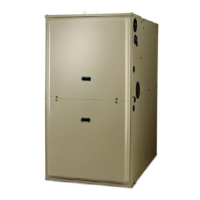
INDUCER ROTATED FOR
LEFT SIDE VENTING
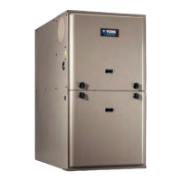
UPFLOW
AS RECEIVED
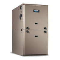
INDUCER ROTATED FOR
RIGHT SIDE VENTING
When drain hose routing changes are required, be sure to cap all un-used openings.
If rerouting hoses - excess length should be cut off so that no sagging loops will collect
and hold condensate, which will cause the furnace to not operate.
Shorten
pressure
switch hose
Re-route and
shorten
pressure
switch hose
Shorten
rain gutter
hose
Move rain
gutter hose
to this position
For 100 & 120K input furnaces, the condensate
drain is plumbed toward the left casing outlet from the factory.
For 060 & 080K input furnaces, the condensate
drain is plumbed toward the right casing outlet from the factory.
Condensate drain may exit cabinet on either side.
1
2
1
2
 Loading...