406905-UIM-C-1009
6 Johnson Controls Unitary Products
SUBCOOLING CHARGING METHOD - TXV INDOOR
For cooling operation, the subcooling values are shown in parentheses
on the charging charts provided with the unit.
1. Set the system running in cooling mode by setting the thermostat
at least 6°F below the room temperature and operate system for at
least 10 – 15 minutes.
2. Refer to the technical guide for the recommended indoor airflow
and verify it is correct (it should be about 400 SCFM per ton).
3. Measure and record the indoor wet bulb (WB) and the outdoor
ambient dry bulb (DB) temperature.
4. Using the charging chart located on the unit, find the intersection
of the indoor wet bulb and the outdoor dry bulb. This is the recom-
mended liquid pressure (and subcooling value).
5. Measure and record the pressure at the liquid valve pressure port
and compare to the value obtained in step 4.
6. Add charge if the measured liquid pressure is lower than the rec-
ommended value. Remove / recover charge if the measured liquid
pressure is above the recommended value.
Condenser subcooling is obtained by calculating the difference of the
saturated refrigerant temperature of the pressure measured at the liquid
base valve and the liquid tube temperature as measured at the liquid
base valve.
Subcooling Temp. (TC) = Saturated Temp. (TS) – Liquid Temp. (T)
SECTION VII: ELECTRICAL
CONNECTIONS
GENERAL INFORMATION & GROUNDING
Check the electrical supply to be sure that it meets the values specified
on the unit nameplate and wiring label.
Power wiring, control (low voltage) wiring, disconnect switches and over
current protection must be supplied by the installer. Wire size should be
sized per NEC requirements.
The complete connection diagram and schematic wiring label is located
on the inside surface of the unit service access panel.
FIELD CONNECTIONS POWER WIRING
1. Install the proper size weatherproof disconnect switch outdoors
and within sight of the unit.
2. Remove the screw from the field wiring access cover on the ser-
vice valve end of the unit. Slide the cover down and remove from
unit.
3. Run power wiring from the disconnect switch to the unit.
4. Route wires from disconnect through power wiring opening pro-
vided and into the top of the field wiring box as shown in Figure 6.
5. Install the proper size time-delay fuses or circuit breaker, and
make the power supply connections.
Example: The liquid pressure listed at the intersection of the indoor
WB and the outdoor DB 320 psig. Pressure at the liquid valve is 305
psig. It would be necessary to add refrigerant to increase the liquid
pressure to 320 psig.
IT IS UNLAWFUL TO KNOWINGLY VENT, RELEASE OR DIS-
CHARGE REFRIGERANT INTO THE OPEN AIR DURING
REPAIR, SERVICE, MAINTENANCE OR THE FINAL DISPOSAL
OF THIS UNIT.
WHEN THE SYSTEM IS FUNCTIONING PROPERLY AND THE
OWNER HAS BEEN FULLY INSTRUCTED, SECURE THE
OWNER’S APPROVAL.
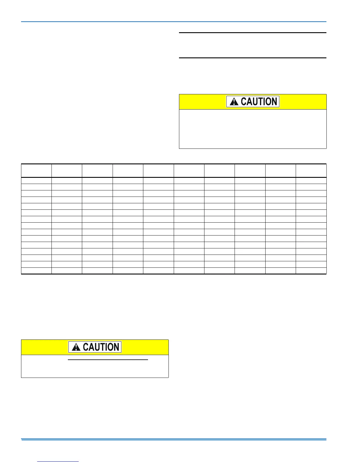
TABLE 2:
R-410A Saturation Properties
TEMP. °F
PRESSURE
PSIG
TEMP. °F
PRESSURE
PSIG
TEMP. °F
PRESSURE
PSIG
TEMP. °F
PRESSURE
PSIG
TEMP. °F
PRESSURE
PSIG
45 130 60 170 75 217 90 274 105 341
46 132 61 173 76 221 91 278 106 345
47 135 62 176 77 224 92 282 107 350
48 137 63 179 78 228 93 287 108 355
49 140 64 182 79 232 94 291 109 360
50 142 65 185 80 235 95 295 110 365
51 145 66 188 81 239 96 299 111 370
52 147 67 191 82 243 97 304 112 375
53 150 68 194 83 247 98 308 113 380
54 153 69 197 84 250 99 313 114 385
55 156 70 201 85 254 100 317 115 391
56 158 71 204 86 258 101 322 116 396
57 161 72 207 87 262 102 326. 117 401
58 164 73 211 88 266 103 331 118 407
59 167 74 214 89 270 104 336 119 412
All field wiring must USE COPPER CONDUCTORS ONLY and be
in accordance with Local, National, Fire, Safety & Electrical Codes.
This unit must be grounded with a separate ground wire in accor-
dance with the above codes.
 Loading...