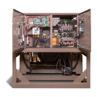
WARNING
External wiring, unless specified as an optional connection in the manufacturer’s product line, is not
to be connected inside the control cabinet. Devices such as relays, switches, transducers and controls
and any external wiring must not be installed inside the micro panel. All wiring must be in accordance
with Johnson Controls’ published specifications and must be performed only by a qualified electrician.
Johnson Controls will NOT be responsible for damage/problems resulting from improper connections
to the controls or application of improper control signals. Failure to follow this warning will void the
manufacturer’s warranty and cause serious damage to property or personal injury.
Changeability of this document
In complying with Johnson Controls’ policy for continuous product improvement, the information
contained in this document is subject to change without notice. Johnson Controls makes no
commitment to update or provide current information automatically to the manual or product
owner. Updated manuals, if applicable, can be obtained by contacting the nearest Johnson
Controls Service office or accessing the Johnson Controls Knowledge Exchange website at https://
docs.johnsoncontrols.com/chillers/.
It is the responsibility of rigging, lifting, and operating/service personnel to verify the applicability
of these documents to the equipment. If there is any question regarding the applicability of these
documents, rigging, lifting, and operating/service personnel should verify whether the equipment
has been modified and if current literature is available from the owner of the equipment prior to
performing any work on the chiller.
Revision notes
Revisions made to this document are indicated in the following table. These revisions are to
technical information, and any other changes in spelling, grammar, or formatting are not included.
Affected pages Description
6 Associated literature table updated
17–19 Compressors updated to Q8 compressors
17–18, 20–21, 23–24 Ring gasket for suction line added to images
26 Compressor weights table updated
31–33
Tables for unit weights, evaporator marine waterbox weights, and
condenser marine waterbox weights updated
Associated literature
Manual description Form number
Installation Checklist/Start-Up Request 160.76-CL1
Unit Start-Up Checklist 160.76-CL2
Installation - Unit 160.76-N1
Installation - MVVSD - 2300 VAC to 6600 VAC 160.00-N6
Installation - MVVSD - 10 kV to 13.8 kV 160.00-N8
Wiring Diagrams - Field Connections - Unit-Mounted SSS or Remote Mounted
MVSSS, MVEMS
160.76-PW1
Wiring Diagrams - Field Connections - Remote Mounted MVSSS 160.76-PW2
Model YK Chillers (Style H) Field Reassembly for Form 3, 7, 9, and 10 Shipment6
 Loading...
