JOHNSON CONTROLS
193
SECTION 9 – SERVICE AND TROUBLESHOOTING
FORM 150.72-ICOM6
ISSUE DATE: 08/03/2022
9
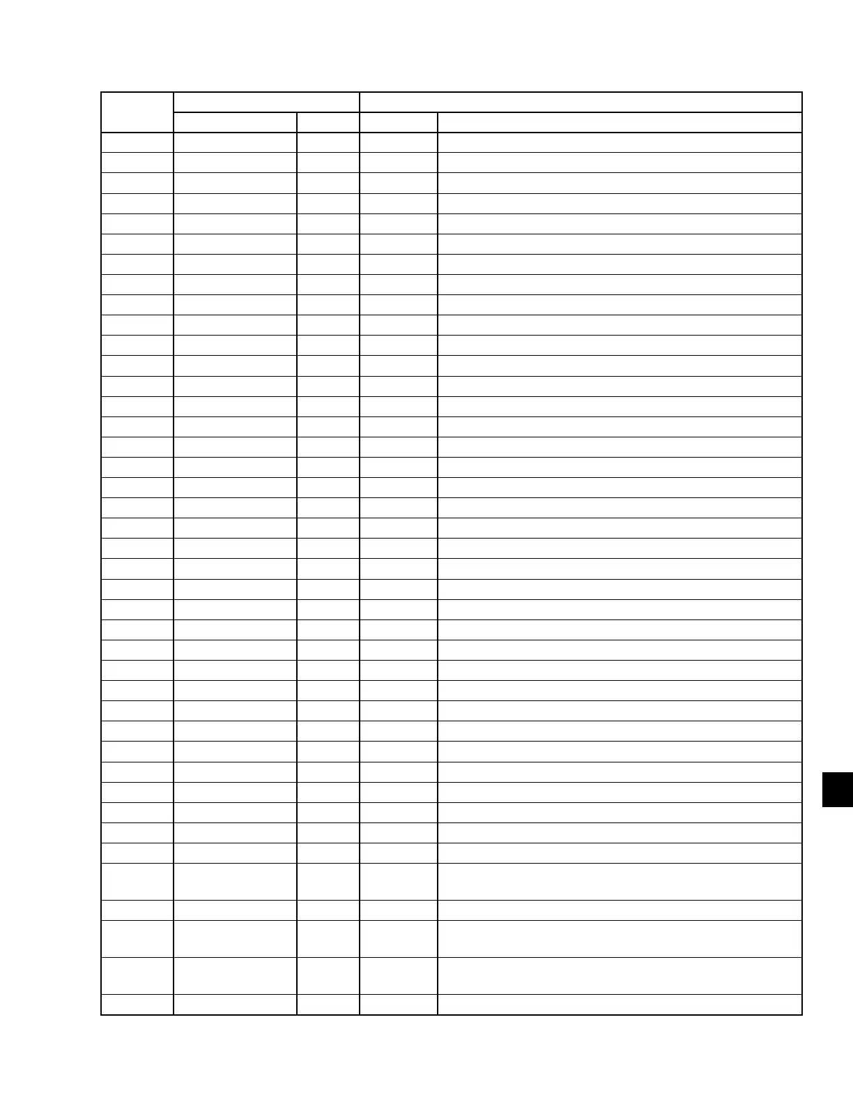
TABLE 35 - DATA LOGGING TO FLASH
DATA
NUMBER
HEADER DATA
TEXT UNIT FORMAT VALUE DESCRIPTION
1 Date x/x/xxxx Date
2 Time x:x:x Time (24 Hour Format)
3 Elapsed Time s x Elapsed time (seconds since data logging started)
4 LCHLT °F x.x Leaving Chilled Liquid Temperature
5 RCHLT °F x.x Return Chilled Liquid Temperature
6 LHLT °F x.x Leaving Hot Liquid Temperature (YCWL)
7 RHLT °F x.x Return Hot Liquid Temperature (YCWL)
8 Ambient Air °F x.x Ambient Air Temperature (N/A YCWL)
9 Active Cool Setp °F x.x Active Cooling Setpoint
10 Active Heat Setp °F x.x Active Heating Setpoint
11 Evap Heater x Evaporator Heater Status
12 Evap Pump x Evaporator Pump Contact Status
13 Evap Pump 2 x Evaporator Pump 2 Contact Status (Hydro Kit 2)
14 Biv Ht Step x Bivalent Heat Step (YLAE)
15 Drip Tray Htr x Drip Tray Heater (YLPA)
16 Mode Select x Mode Select (YCWL) (0=Chiller, 1=Heatpump)
17 Lead System x Lead System (0=System1, 1=System2)
18 Flow Switch x Flow Switch Status
19 S1 Run Time s x Sys 1 Run Time
20 S1 Operating Code x Sys 1 Operational Code
21 S1 Fault Code x Sys 1 Fault Code
22 S1 Suct Press psig x.x Sys 1 Suction Pressure
23 S1 Act_Spc psig x.x Sys 1 Actual Suction Pressure Cutout
24 S1 Dsch Press psig x.x Sys 1 Discharge Pressure
25 S1 Suct Temp °F x.x Sys 1 Suction Temperature
26 S1 Sat Suct Temp °F x.x Sys 1 Saturated Suction Temperature
27 S1 Suct Sheat °F x.x Sys 1 Suction Superheat
28 S1 C1 Run x Sys 1 Compressor 1 Run Status
29 S1 C2 Run x Sys 1 Compressor 2 Run Status
30 S1 C3 Run x Sys 1 Compressor 3 Run Status
31 S1 LLSV x Sys 1 Liquid Line Solenoid Valve Status
32 S1 Hot Gas x Sys 1 Hot Gas Bypass Solenoid Valve Status
33 S1 Fan Stage x Sys 1 Condenser Fan Stage
34 S1 Fan Speed % x Sys 1 VSD Fan Speed (VSD Fans)
35 S1 Comp Seq x Sys 1 Programmed Compressor Sequence (1=C1, 2=C2, 3=C3)
36 S1 CIR Temp °F x.x Sys 1 Cooler Inlet Refrig. Temp (R-407c)
37 S1 Dsch Sheat °F x.x Sys 1 Discharge Superheat (discharge temperature sensors
enabled)
38 S1 Sheat Setp °F x.x Sys 1 Superheat Setpoint
39 S1 Dsch Temp °F x.x
Sys 1 Discharge Temperature (discharge temperature sensors
enabled)
40 S1 EEV Cmd %
x
x.x
Sys 1 EEV Command (0 – 100%) 031-02755-001, -003
Sys 1 EEV Command (0.0 – 100.0%) 031-02755-004
41 S1 EEV PWM % x Sys 1 EEV PWM (0 – 100%) 031-02755-001, -003
 Loading...
