JOHNSON CONTROLS
75
SECTION 6 - MAINTENANCE
FORM 160.67-O2
ISSUE DATE: 10/9/2020
6
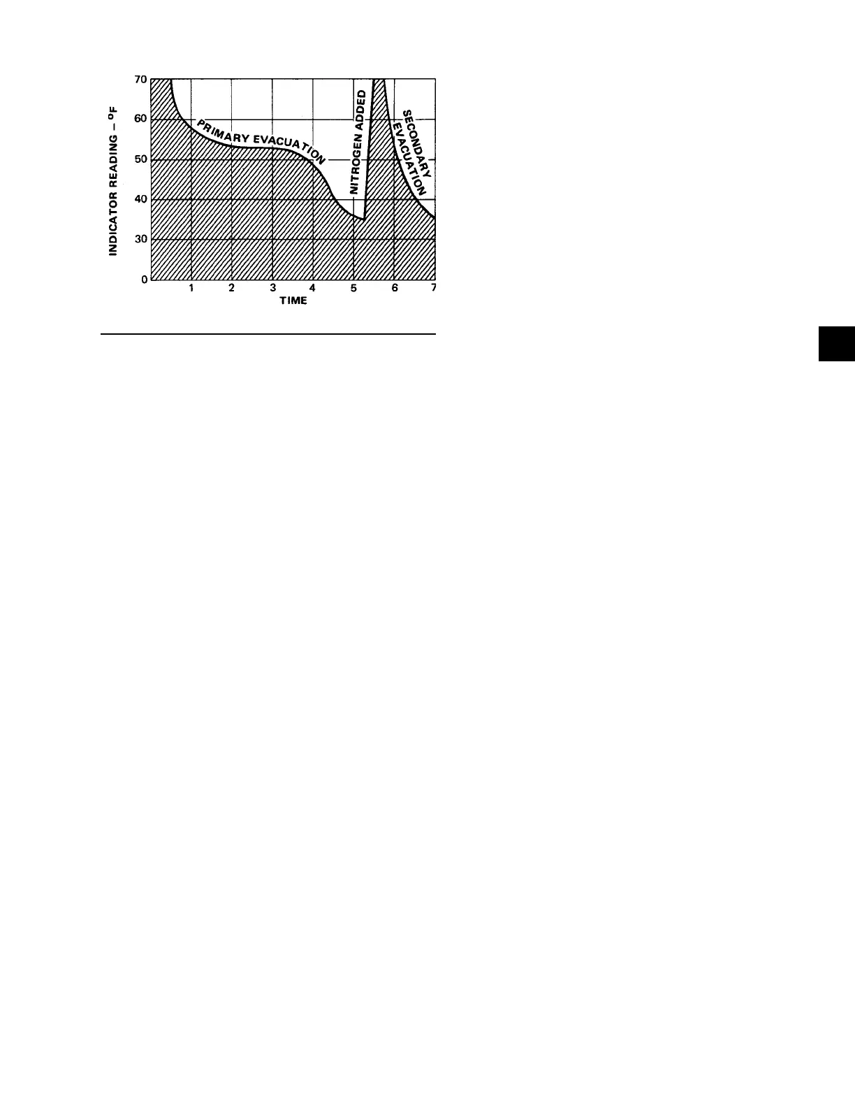
FIGURE 19 - SATURATION CURVE
LD00474
The equipment required to follow this method of de-
hydration consists of a wet bulb indicator or vacuum
gauge, a chart showing the relation between dew point
temperature and pressure in inches of mercury (vacu-
um), (See Table 4 on page 73) and a vacuum pump
capable of pumping a suitable vacuum on the system.
OPERATION
Dehydration of a refrigerant system can be obtained
by this method because the water present in the system
reacts much as a refrigerant would. By pulling down
the pressure in the system to a point where its satu-
ration temperature is considerably below that of room
temperature, heat will flow from the room through the
walls of the system and vaporize the water, allowing
a large percentage of it to be removed by the vacuum
pump. The length of time necessary for the dehydra-
tion of a system is dependent on the size or volume of
the system, the capacity and efficiency of the vacuum
pump, the room temperature and the quantity of water
present in the system. By the use of the vacuum indi-
cator as suggested, the test tube will be evacuated to
the same pressure as the system, and the distilled water
will be maintained at the same saturation temperature
as any free water in the system, and this temperature
can be observed on the thermometer.
If the system has been pressure tested and found to be
tight prior to evacuation, then the saturation tempera-
ture recordings should follow a curve similar to the
typical saturation curve shown as Figure 19 on page
75.
The temperature of the water in the test tube will drop
as the pressure decreases, until the boiling point is
reached, at which point the temperature will level off
and remain at this level until all of the water in the
shell is vaporized. When this final vaporization has
taken place the pressure and temperature will continue
to drop until eventually a temperature of 35°F (1.6°C)
or a pressure of 5 mm Hg. is reached.
When this point is reached, practically all of the air
has been evacuated from the system, but there is still a
small amount of moisture left. In order to provide a me-
dium for carrying this residual moisture to the vacuum
pump, nitrogen should be introduced into the system to
bring it to atmospheric pressure and the indicator tem-
perature will return to approximately ambient tempera-
ture. Close off the system again, and start the second
evacuation.
The relatively small amount of moisture left will be
carried out through the vacuum pump and the tem-
perature or pressure shown by the indicator should
drop uniformly until it reaches a temperature of 35°F
(1.6°C) or a pressure of 5 mm Hg.
When the vacuum indicator registers this temperature
or pressure, it is a positive sign that the system is evac-
uated and dehydrated to the recommended limit. If this
level cannot be reached, it is evident that there is a leak
somewhere in the system. Any leaks must be corrected
before the indicator can be pulled down to 35°F or 5
mm Hg. in the primary evacuation.
During the primary pulldown, keep a careful watch on
the wet bulb indicator temperature, and do not let it fall
below 35°F (1.6°C). If the temperature is allowed to
fall to 32°F (0°C), the water in the test tube will freeze,
and the result will be a faulty temperature reading.
REFRIGERANT CHARGING
To avoid the possibility of freezing liquid within the
evaporator tubes when charging an evacuated system,
only refrigerant vapor from the top of the drum or cyl-
inder must be admitted to the system pressure until the
system pressure is raised above the point correspond-
ing to the freezing point of the evaporator liquid. For
water, the pressure corresponding to the freezing point
is 8.54 PSIG (58.9 kPa) for R-134a (at sea level).
While charging, every precaution must be taken to pre-
vent moisture laden air from entering the system. Make
up a suitable charging connection from new copper
tubing to fit between the system charging valve and the
fitting on the charging drum. This connection should be
as short as possible but long enough to permit sufficient
flexibility for changing drums. The charging connec-
tion should be purged each time a full container of re-
frigerant is connected and changing containers should
be done as quickly as possible to minimize the loss of
refrigerant.
 Loading...


