7
■ Keep about 1 meter distance between zelsius
®
C5-CMF and electromagnetic sources of inter-
ference like switch cabinets, motors or pumps.
Keep about 0.2 m distance to power cables.
Keep min. 3 cm free mounting space around
the device.
Notes ball valves
■ Mount ball valves up- and downstream of the
meter.
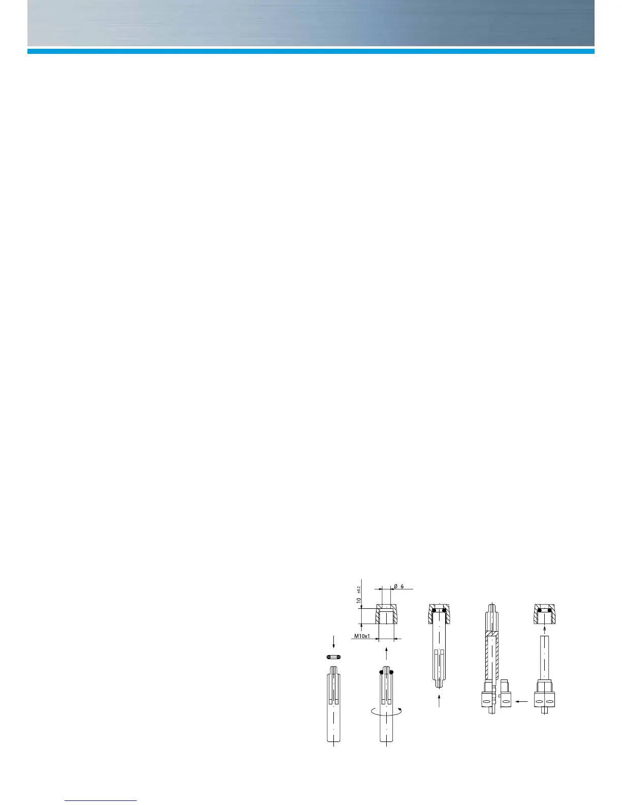
■ Mount a ball valve with bore M10x1 for direct
sensors in the supply. This is required for the
installation of the supply sensor.
■ For symmetrical temperature sensor installa-
tion, mount an identical ball valve in the return.
Mounting heating / cooling energy meter
■ Flush the system thoroughly before installing
the heating energy meter.
■ Close valves and release pressure.
■ Screw out the overow cap (2) or the existing
measuring capsule.
■ Check the seal face and thread on the measur-
ing capsule and the EAS for damage.
■ Remove the old prole seal, clean the seal
face and insert the new one (3) into the EAS
(4) with the at side up.
■ Attention: insert only one prole seal! The O-
ring on the meter’s lter must be tted into the
groove. Use only new and awless sealing
material.
■ Use only new and awless sealing material.
■ Remove the protective cap (1) from the new
measuring capsule (5) and then screw into the
EAS (4).
■ Tighten measuring capsule up to the metallic
stop with a hook wrench (for example: accord-
ing to DIN 1810 A, 68-75 mm).
■ Turn heat calculator to desired reading position.
Information: The best measuring results can be
achieved by mounting with horizontal diallevel.
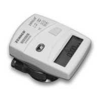
Combi-devices are, for example, used in tight
installation points without room for the calculator
on the ow sensor or when the calculator is dif-
cult to read.
Installing the temperature sensor
■ The installation of the temperature sensors
should be preferably symmetrical and direct
installation.
■ Do not remove the return sensor if already
mounted in the VMU.This is also valid for all
the safety seals which are mounted on the de-
vice as standard.
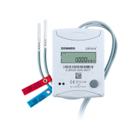
■ Sensors are colour-coded (red = supply, blue
= return).
■ The connecting cables may not be buckled, ex-
tended or shortened.
■ The seal at the sensor installation point on the
measuring capsule may not be damaged.
■ Remove locking screw and seal at the ball
valve completely, if existing.
Montage DF- Adapter
 Loading...