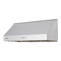
Do you have a question about the Zephyr LAYERS WALL DLA-E42ASSX and is the answer not in the manual?
| Type | Wall Mount |
|---|---|
| Width | 42 inches |
| Airflow | 600 CFM |
| Lighting | LED |
| Finish | Stainless Steel |
| Number of Fan Speeds | 3 |
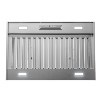
| Filter Type | Baffle |
| Duct Type | Round |
| Control Type | Electronic Touch |
| Venting Options | Ducted |
| Controls | Electronic |
Essential guidelines for safe operation and installation of the range hood.
Specifies that the appliance is intended for residential applications.
Encourages users to read and retain instructions for future reference.
Warning against using the fan with solid-state speed control devices.
Emphasizes the need to vent exhaust air outdoors and not into walls or ceilings.
Limits use to general ventilation, prohibiting exhaust of hazardous materials.
Advises protecting the motor from construction dust and debris to prevent damage.
Outlines critical safety measures for users and installers.
Provides specific warnings and advice related to range top grease fires.
Recommends operating the hood during high-heat or flambé cooking.
Stresses frequent cleaning of fans and filters to prevent grease buildup.
Detailed instructions on how to respond to a range top grease fire.
Important safety warnings specific to the installation process.
Explains the importance of sufficient air for fuel-burning equipment.
Caution against damaging electrical wiring or utilities during installation.
Mandates that all ducted fans must be vented to the outdoors.
States the necessity of grounding the unit for electrical safety.
Warning to use only metal ductwork to reduce fire risk.
General warnings about potential dangers with domestic appliances.
Details important electrical specifications and installation requirements.
Advises against placing fuses in neutral or ground circuits.
Specifies the required voltage, frequency, and circuit protection for the appliance.
Information regarding FCC compliance for potential radio frequency emissions.
Warning about chemicals in the product that may cause cancer or reproductive harm.
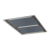
Lists the specific parts included for the DLA-E42ASSX and DLA-M90ASSX models.
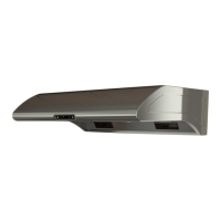
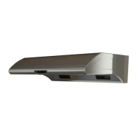
Lists the specific parts included for the DVS-E30ASSX and DVS-E36ASSX models.
Specifies the maximum allowable equivalent duct length for optimal performance.
Dimensions for standard ducted and recirculating installations.
Dimensions for the Z1C-00VS model installation.
Frontal dimensions of the range hood.
Side profile dimensions of the range hood.
Top view dimensions of the range hood.
Rear view dimensions of the range hood.
Dimensions for standard ducted and recirculating installations for DVS models.
Dimensions for the Z1C-00VS model installation for DVS models.
Frontal dimensions of the DVS range hood.
Side profile dimensions of the DVS range hood.
Top view dimensions of the DVS range hood.
Rear view dimensions of the DVS range hood.
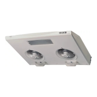
Specifies compatible internal blower models for safe installation.
Directs users to another section for external/in-line blower preparation.
Step 1: Remove the 6-inch round metal knockout plate from the blower plate.
Step 2: Unscrew and remove the blower plate from the blower housing.
Step 3: Mount the internal blower into the blower plate and secure it.
Step 4: Attach the capacitor box and cable to the blower plate.
Step 5: Connect the green/yellow ground wire to the provided capacitor.
Step 6: Connect the 6-pin male molex connector from the blower wire.
Step 7: Install the blower and plate into the housing, completing installation.
Step 8: Connect the 9-pin molex connector from the blower wire to the capacitor wire.
Critical warning to keep all electrical wiring inside the motor housing.
Indicates the unit is prepared for final wall installation.
Caution to use remote blowers rated at a maximum of 6.2 A.
Directs users to internal blower installation instructions on page 13.
Step 1: Unscrew and remove the blower plate from the blower housing.
Step 2: Modify blower plate by attaching a rectangular plate for duct connection.
Step 3: Reinstall the blower plate into the blower housing.
Step 4: Remove specific knock-out plates for remote blower connection.
Step 5: Secure the 8-inch round blower collar to the top of the blower housing.
Step 6: Connect the 6-pin female molex connector and secure the junction box.
Step 7: Feed the wire harness through the junction box cover and connect wires.
Note on adhering to national electric code for power supply connection.
Step 8: Secure the junction box cover with screws.
Note on potential requirement for a cable lock based on local codes.
Step 9: Connect male molex connectors to female molex connectors inside the housing.
Note to check local codes for determining the minimum wire gauge.
Refers to a separate manual for installing the external/in-line blower itself.
Warning about fire hazards associated with improper ductwork termination.
Prohibits terminating ductwork into enclosed building spaces.
Mandates outdoor venting for exhaust, except for recirculating setups.
Specifies the use of single-wall rigid metal ductwork exclusively.
Instructions on fastening duct connections with screws and tape.
Illustrates various common ducting arrangements.
Specifies the minimum and maximum recommended installation heights.
Sets the minimum installation height requirement from the cooking surface.
Warning against connecting the hood's duct to another appliance's exhaust.
Step-by-step guide for physically mounting the hood onto the wall.
Step 1: Use the provided template to mark screw locations on the wall.
Step 2: Lift the hood onto the screws and ensure it is level.
Step 3: Tighten screws to securely fasten the hood in its final position.
Note recommending fastening screws into wall studs for secure mounting.
Advise on using wall-appropriate screws and anchors, specifying minimum size.
General information regarding installation safety and maintenance for power connection.
Detailed steps for connecting the unit to the main power source.
Step 1: Lift and secure the bottom part of the duct cover with tape.
Step 2: Remove the power supply cover by unscrewing it.
Step 3: Make a hole in the box cover for the power supply conduit.
Step 4: Attach the power supply conduit to the cover.
Step 5: Connect the hood's wires (black, white, ground) to the power supply.
Requirement to install a properly rated double-pole switch for disconnection.
Connect the electrical conduit to the field wiring compartment using fittings.
Ensure power supply connection complies with national electric code standards.
Step 6: Place wires in the box, close cover, and secure with screws.
Step 7: Remove tape from chimney and attach the lower part to the hood.
Step-by-step process for mounting the duct cover.
Step 1: Test electrical functions before installing duct covers.
Step 2: Install air diverter for recirculating mode before duct covers.
Step 3: Adjust the bracket width to fit the chimney top.
Step 4: Attach the duct cover bracket to the wall below the ceiling.
Step 5: Place ducting over the hood collar and secure with tape.
Step 6: Join the top and bottom duct covers, ensuring correct seating.
Step 7: Extend and secure the top duct cover to the bracket.
Describes the operation of the lights button for adjusting brightness levels.
Explains the delay off function, its activation, and deactivation.
Details the power button's role in activating standby mode and turning the unit off.
Describes how to select low fan speed from standby mode.
Describes how to select medium fan speed from standby mode.
Describes how to select high fan speed from standby mode.
Explains the indicator for mesh filter cleaning and how to reset it.
Details how to enable, use, and reset the charcoal filter replacement reminder.
Describes how to enable and use the Clean Air function for air purification.
Steps to synchronize the remote control with the range hood.
Provides general information about the remote's range, storage, and care.
Instructions for replacing the batteries in the remote control.
Advises running the appliance before cooking and for 5 minutes after.
Recommends cleaning mesh filters every 2 months or when indicated.
Detailed instructions on how to wash and dry the mesh filters.
Guidelines for cleaning the blower and other surfaces of the hood.
Lists components available as replacements.
Lists optional items that can enhance the hood's functionality.
Provides contact and website details for ordering parts and accessories.
Contact information for obtaining warranty service and support.
Covers free replacement parts for two years from the original purchase date.
Covers free labor costs for one year from the original purchase date.
Lists specific conditions and situations not covered by the warranty.
Outlines limitations on remedies and disclaims liability for consequential damages.
Procedures and requirements for qualifying for warranty service.
Explains why prompt product registration is important for users.