5 Electrical installation
5.1 Safety precautions
Danger due to electric current
•
Work on electric components may only be carried out by trained electricians or by persons
instructed in electricity under the supervision of an electrician in accordance with electrical
engineering regulations.
•
It is forbidden to carry out work on electrically live parts.
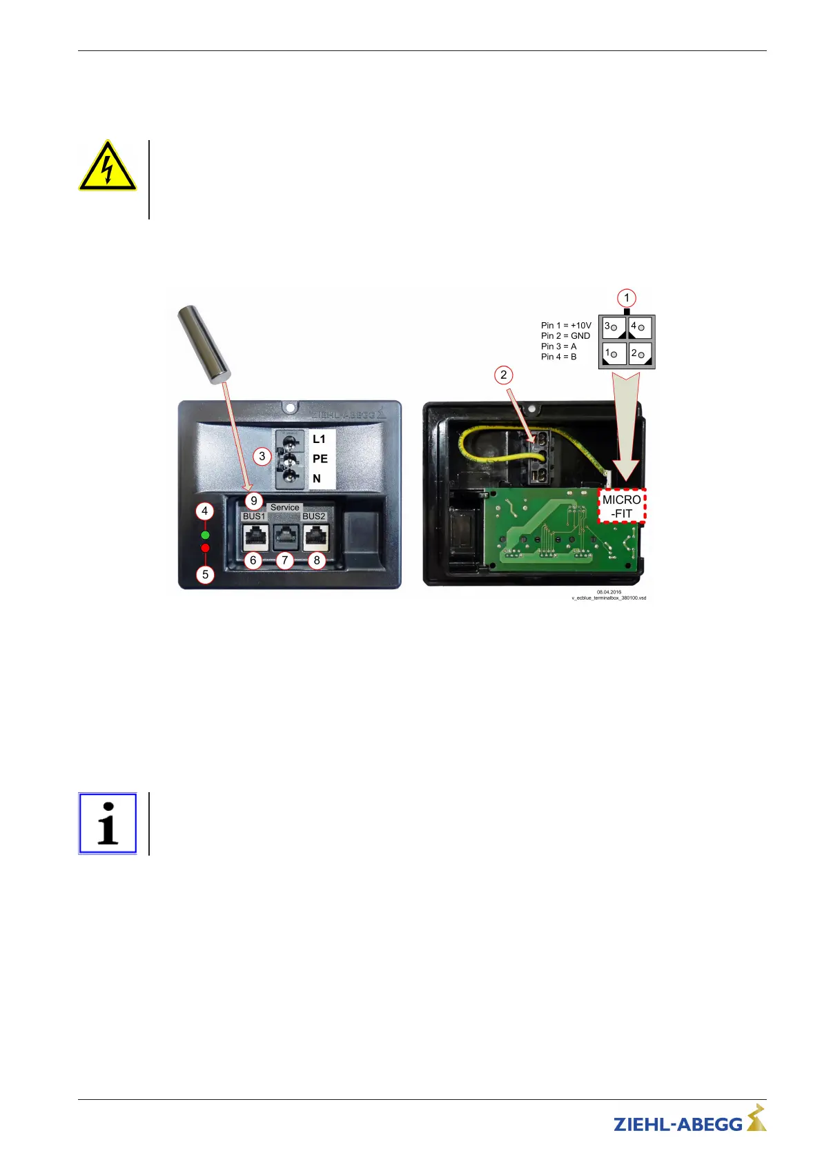
5.2 Connection components
Front view Back
1 Fan control connection (MICRO-FIT, max. connection cross-section: 0.14 mm
2
/ AWG26). The LEDs on the connection box
are supplied from the connected fan (output voltage +10 V).
2 Connection line fan (tension clamp connection 0.5 - 1.5 mm
2
flexible with wire end ferrule)
3 Line input connection box (Wieland plug series GST 18i3, suitable socket part e.g. GST 18i3 S B1 Z R1 or GST 18i3 1 F B2
Z R1)
4 LED green = Operation / Flashing error code (see ECblue assembly instructions, chapter “Operating state display”)
5 LED red = Fault (see ECblue assembly instructions, chapter “operating state display”)
6 BUS1 (RJ45)
7 Service (RJ45)
8 BUS2 (RJ45)
9 HALL sensor for "service pin". To trigger the "service pin", position the bar magnet (item no. 00161444) in the left corner.
Information
" As an option, the service pin can be triggered with a 5 V pulse (typical duration 0.5 s)
at “V+” and “V-”.
" The fan must be set to the address of 247, otherwise no communication!
Operating Instructions Connection box ECblue (LON) Electrical installation
L-BAL-E268-GB 1630 Index 003 Part.-No.
4/10
 Loading...