fi
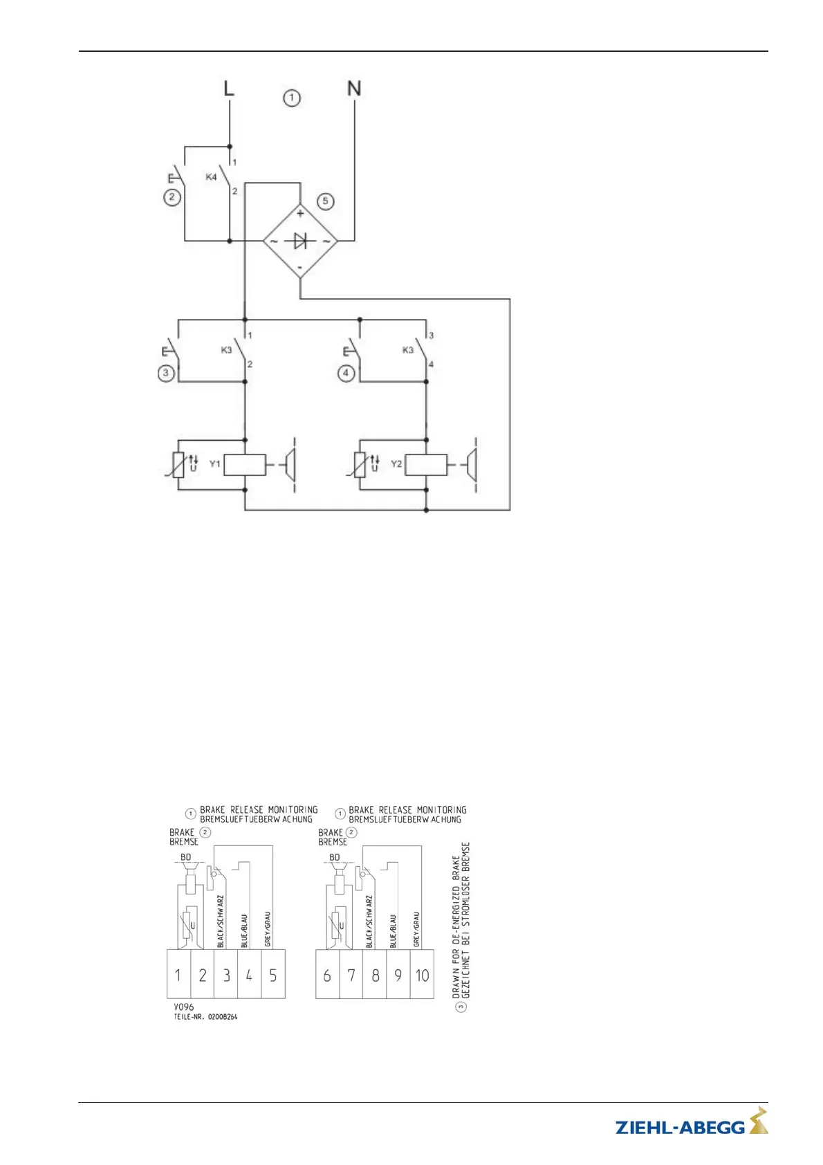
1 Voltage supply
2 Button two circuit test
3 / 4 “Open brake” button
5Rectifier
K3 Brake contactor, activated by safety circuit
K4 Brake contactor, activated by control or frequency inverter
5.5.5 Connection
•
•
•
5.5.6 Connection diagram
1 Brake release monitoring
2Brake
3 Shown with currentless brake
ZAtop–

 Loading...