Page 6 of 12 Zip Hydroboil - Installation & Operating Instructions - 85264 - May 2012 v1.00
Step 3 – Connecting
a) Plumbing
For exposed plumbing connection, connect the cold water inlet pipe from the
base of the heater directly to the 15 mm or half-inch compression fittings with
the nuts and olives provided.
For concealed plumbing connections, connect the cold water pipe through the
rear of the chassis using a 15 mm or half-inch capillary elbow.
Cold water pipes must be flushed before connection to the inlet. Any clogging
due to sediment or fines will adversely affect the operation of the heater.
It is recommended that the heater be installed with a stop cock which allows it
to be isolated from the mains supply for servicing.
Water pressure requirements:
Minimum - 1.0 bar, (100 kPa) maximum - 7 bar (1000 kPa).
Warning: If pressure is likely to exceed 7 bar, a pressure limiting valve must be
installed in the cold water supply line. Zip recommends a valve rated at 3.5 bar
(350 kPa) for this application.
b) Venting
A vent at the base of the heater must be plumbed to a safe visible location as,
under certain conditions, it may discharge cold or boiling water and/or steam.
For exposed vent plumbing, connect vent outlet from the base of heater to a
15 mm or half inch OD pipe which has a continuous fall, is no more than 3
metres long, has no more than 3 right angle bends, and discharges to a waste
water drain.
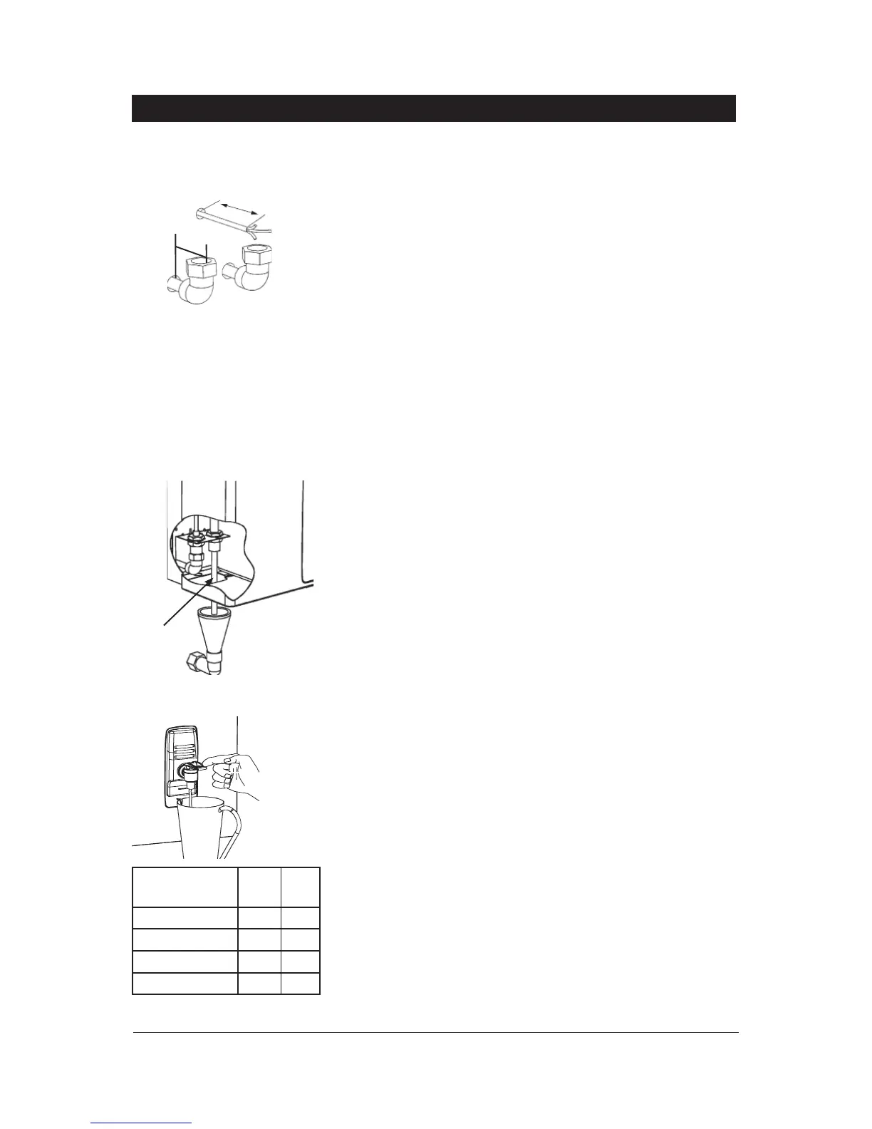
For concealed vent plumbing, connect plumbing to the vent outlet from the
heater rear using a capillary elbow protruding 45 mm from the wall.
Alternatively attach a tun dish to the wall as shown and plumb away to waste.
d) Electrical
For concealed electrical connection, connect a power cable through the rear
access opening of the heater to the terminal block within the heater as shown.
For exposed electrical connection, connect a flex to a standard 13 amp double
pole fused spur power outlet on the wall within 1500 mm of the heater.
All isolation switches must have a contact seperation of at least 3 mm in all poles.
Do not turn the power ON until the heater is filled with water.
Step 4 – Assembling
Place the heater case back on to the heater and secure the top 2 case screws.
Secure two bottom case screws.
Step 5 – Commissioning
Check previous steps. Turn water supply ON. Water is now flowing into heater,
check connections for leaks. Wait approximately 5 minutes and check outlet
tap for water. This is acheived by pulling the tap handle forward.
Power is only to be turned on when water is available from this outlet.
Turn power ON. After a short period, boiling water will be available and will be
maintained close to boiling point thereafter. Initial heating periods are shown in
the table on the left.
Installation Procedures Continued
250mm
Wring
Concealed
Vent
Concealed
Inlet
45 mm
Visible TundishVent line
Inlet water
temperature
15°C 10°C
1.5 Litre models 10 min 11 min
3.0 Litre models 16 min 17 min
5.0 Litre models 16 min 17 min
7.5 Litre models 23 min 24 min
 Loading...