Home
Zte
Network Router
ZXR10 ZSR
Zte ZXR10 ZSR User Manual
4
of 1
of 1 rating
67 pages
Give review
Manual
Specs
To Next Page
To Next Page
Loading...
ZXR10
ZSR
Intelligent
Integrated
Multi-Service
Router
Hardware
Installation
Manual
V
ersion:
V2.8.1
1
ZTE
CORPORA
TION
NO.
55,
Hi-tech
Road
South,
ShenZhen,
P
.R.China
Postcode:
518057
T
el:
+86-755-26771900
Fax:
+86-755-26770801
URL:
http://ensupport.zte.com.cn
E-mail:
support@zte.com.cn
2
Table of Contents
Default Chapter
3
Table of Contents
3
About this Manual
5
Chapter 1 Safety Instructions
7
Safety Introduction
7
Safety Description
7
Table 1-1 SAFETY DESCRIPTION
7
Chapter 2 Installation Overview
9
Equipment Configuration
9
Installation Content
9
Equipment Composition
9
Figure 2-1 ZXR10 ZSR Installation Sketch Map
9
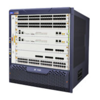
Main Device
10
Table 2-1 ZXR10 ZSR Series Models
10
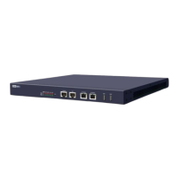
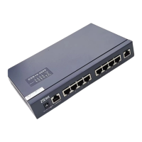
Figure 2-2 ZXR10 ZSR (1U) Front View
11
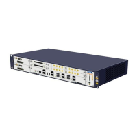
Figure 2-3 ZXR10 ZSR (2U) Front View
11
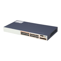
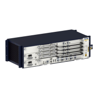
Figure 2-4 ZXR10 ZSR (3U) Front View
12
Figure 2-5 ZXR10 ZSR 1809 (Soho) Front View
12
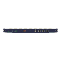
Figure 2-6 ZXR10 ZSR R (Compact Model) (1U) Front View
12
Hardware Installation Flow
13
Figure 2-7 ZXR10 ZSR R (Compact Model) (2U) Front View
13
Table 2-2 ZXR10 ZSR Device Parameters
13
Table 2-3 Newly Added ZXR10 ZSR Device Parameters
13
Figure 2-8 Hardware Installation Flow Diagram
14
Figure 2-9 Main Device Installation Flow Diagram
15
Chapter 3 Installation Preparation
17
NOC Room Inspection
17
Figure 3-1 Lab Plane Layout
17
Indoor Environment of NOC Room Inspection
18
Table 3-1 Temperature and Humidity Requirements
19
Power Supply Requirements Inspection
21
Grounding Inspection
21
Auxiliary Equipment Inspection
21
Required Tools
21
Technical Document Preparation
22
Chapter 4 Cabinet Installation
23
Installing a 19" Standard Rack
23
Figure 4-1 Enclosure Installation
24
Chapter 5 Installing the Worktable
25
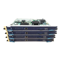
Installing the Board
25
Chapter 6 Power Cables and Grounding Wires Installation
27
AC Power Cable Installation
27
DC Power Cable Installation
27
Figure 6-1 AC Power Cable
27
Figure 6-2 DC Power Cable
27
Grounding Wire Installation
28
Table 6-1 Corresponding Relationship between Two Ends of DC Power Cable
28
Chapter 7 External Cable Installation
29
External Cable Types
29
Configuration Cable Installation
29
Console Cable Installation
29
Figure 7-1 Serial Console Cable
29
Table 7-1 Serial Console Cable Connection
30
AUX Port Cable Installation
31
Ethernet Cable Installation
31
Figure 7-2 Structure of Network Cable with RJ45 Connectors at both Ends
31
Table 7-2 DB9-RJ45_AUX Cable Connection
31
E1 Cables Installation
32
120Ω Twisted Pair Installation
32
Table 7-3 Straight-Through Network Cable RJ45 Connection
32
Table 7-4 Crossover Network Cable RJ45 Connection
32
120ΩE1 (DB44) Cable Installation
33
Table 7-5 Connection Relationship at the Ends of E1 Crossover Cable RJ48
33
Table 7-6 Connection Relationship of RJ48 Connectors at Two Ends of Straight-Through E1 Cable
33
Table 7-7 Line Order at DB44 Interface
34
Coaxial Cable Installation
35
E1 (DB44+BNC) Cable Installation
36
USB Prolong Cable Installation
36
Fiber Installation
36
Figure 7-3 8-Core Micro Coaxial Cable
36
Figure 7-4 USB Extension Cable
36
V.35/V.24 Cable Installation
37
Cable Installation
37
Figure 7-5 V.35C Cable
38
Table 7-8 V.35C1 Cable Connection
38
Figure 7-6 V.35DA Cable
39
Table 7-9 V.35DA Cable Connection
39
Cable Installation
40
Figure 7-7 V.24AA Cable
40
Figure 7-8 V.24BA Cable
41
Table 7-10 V.24AA Cable Connection
41
Figure 7-9 V24A RJ45 Cable
42
Table 7-11 V.24BA Cable Connection
42
Table 7-12 V24A RJ45 Cable Connection
43
Figure 7-10 V24A DB9 Cable
44
Table 7-13 V24A DB9 Cable Connection
45
Figure 7-11 MODEM Cable
46
Table 7-14 MODEM Cable Connection
47
SCSI-V.24 Cable Installation
48
Figure 7-12 V.24-DS-001 Cable
49
Table 7-15 V.24-DS-001 Cable Connection
49
Figure 7-13 V.24-DS-002 Cable
51
Table 7-16 V.24-DS-002 Cable Connection
51
Figure 7-14 V.24-DS-003 Cable
53
Table 7-17 V.24-DS-003 Cable Connection
53
Figure 7-15 SCSI 68 Plug and DB9 Female Plug Multi-Core Cable
54
Table 7-18 SCSI 68 Plug and DB9 Female Plug Multi-Core Cable Connection
55
Label Style
58
Figure 7-16 Transverse English Labels on Panels and Plugs
58
Figure 7-17 Roll-Up Self-Mulching Laser Print Type II Labels
59
Figure 7-18 Power Cable Label
59
Figure 7-19 Paste Position of Power Cable Label
60
Chapter 8 Hardware Installation Inspection
63
Cabinet Inspection
63
Power Cable Inspection
63
Cabling Inspection
64
Label Inspection
64
Figures
65
Tables
67
Other manuals for Zte ZXR10 ZSR
Hardware Manual
59 pages
4
Based on 1 rating
Ask a question
Give review
Questions and Answers:
Need help?
Do you have a question about the Zte ZXR10 ZSR and is the answer not in the manual?
Ask a question
Zte ZXR10 ZSR Specifications
General
Brand
Zte
Model
ZXR10 ZSR
Category
Network Router
Language
English
Related product manuals
Zte ZXR10 ZSR V2
313 pages
Zte ZXR10 ZSR V2 Series
86 pages
Zte ZXR10
117 pages
Zte ZXR10 GER
412 pages
Zte ZXR10 2600
23 pages
Zte ZXR10 T600
83 pages
Zte ZXR10 3800-8
146 pages
Zte ZXR10 2800-4
146 pages
Zte ZXR10 1800-2S
146 pages
Zte ZXR10 M6000 Series
57 pages
Zte ZXHN F660
14 pages
Zte ZXV10 W300
43 pages