!
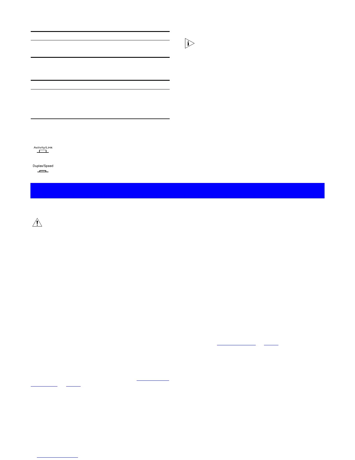
When the Display Function switch is pressed in, these LEDs
show the speed status of each port:
4
Power/Self Test LED
The Power/Self test LED shows the power status of the Switch:
5
Display Function Switch
This switch affects the Status LEDs described in 2 and 3.
6
Self-adhesive Pads
The unit is supplied with four self-adhesive rubber pads.
You do not need to apply the pads if you intend to rack
mount the unit.
If the unit is to be part of a free standing stack, apply the pads to
each marked corner area on the underside of the unit. Place the
unit on top of the lower unit, ensuring that the pads locate with
the recesses of the lower unit.
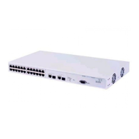
Rear Panel Connections
7
Power Supply
The Baseline 10/100 Switch automatically adjusts to the supply
voltage. Only use the power cord that is supplied with the
Baseline 10/100 Switch.
8
Socket for Redundant Power System (RPS)
Only connect a 3Com SuperStack 3 Advanced RPS (3C16070,
3C16071, 3C16071A or 3C16071B) to this socket. An
appropriate power module and cable is required. The connector
on the Baseline 10/100 Switch is a Type 1, 60W socket. For
details, follow the installation instructions in the guides that
accompany the Advanced RPS and the power module.
Positioning the Baseline 10/100 Switch
CAUTION: If installing the Baseline 10/100 Switch in a
stack of different size SuperStack 3 units, the smaller
units must be installed above the larger ones. Do not
have a free standing stack of more than six units.
When deciding where to position the Baseline 10/100 Switch
ensure:
!
It is accessible and cables can be connected easily.
!
Cabling is away from sources of electrical noise such as
radios, transmitters and broadband amplifiers, and away from
power lines and fluorescent lighting fixtures.
!
Water or moisture cannot enter the case of the unit.
!
Air flow around the unit and through the vents in the side of
the case is not restricted (3Com recommends that you
provide a minimum of 25 mm (1 in.) clearance).
To prolong the operational life of your units:
!
Never stack units more than six high if free standing, and
ensure that cables are supported so that they do not cause
the stack to fall over.
!
Do not place objects on top of any unit or stack.
!
Do not obstruct any vents at the sides of the case.
Rack Mounting
The Baseline 10/100 Switch can be mounted in a 19-inch
equipment rack using the Mounting Kit. Refer to “
Mounting Kit
Instructions” on page 5.
Power Up
Use the following sequence to power up the Baseline 10/100
Switch:
!
Check the network connections and cables.
!
Connect the power supply cable to the appropriate power
socket on the rear panel of the unit; refer to 7 or 8.
!
Connect the plug to the power supply outlet socket and
switch on the power supply at the socket. If you are using
the Advanced Redundant Power System, ensure it is powered
on.
When the switch is powered on, the Power/Self Test LED should
first flash green, then stay lit. If it does not, refer to 4.
Spot Checks
At frequent intervals you should visually check the Baseline
10/100 Switch. Regular checks can give you an early warning of a
possible failure; any problems can then be attended to when
there will be least effect on users. Check that all external cabling
connections are secure and that no cables are pulled taut.
If you experience any problems operating the Baseline 10/100
Switch, refer to “
Problem Solving” on page 5.
Status Meaning
Green The link is operating at 100 Mbps.
Off If the link is present, it is operating at 10 Mbps.
Status Meaning
Green The unit is powered on and ready for use.
Off The unit is not receiving power:
■
Check the power cord is connected correctly.
■
If the unit still does not operate, contact your supplier.
Out
This is the normal position of the switch.
The Status LEDs show the Activity and Link Status of
each port.
In
When the switch is pressed in, the Status LEDs show
the Duplex and Speed Status of each port. The switch
returns to the out position when released.
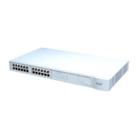
INSTALLING THE SWITCH
!
3
 Loading...