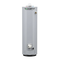
7
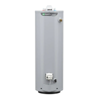
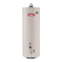
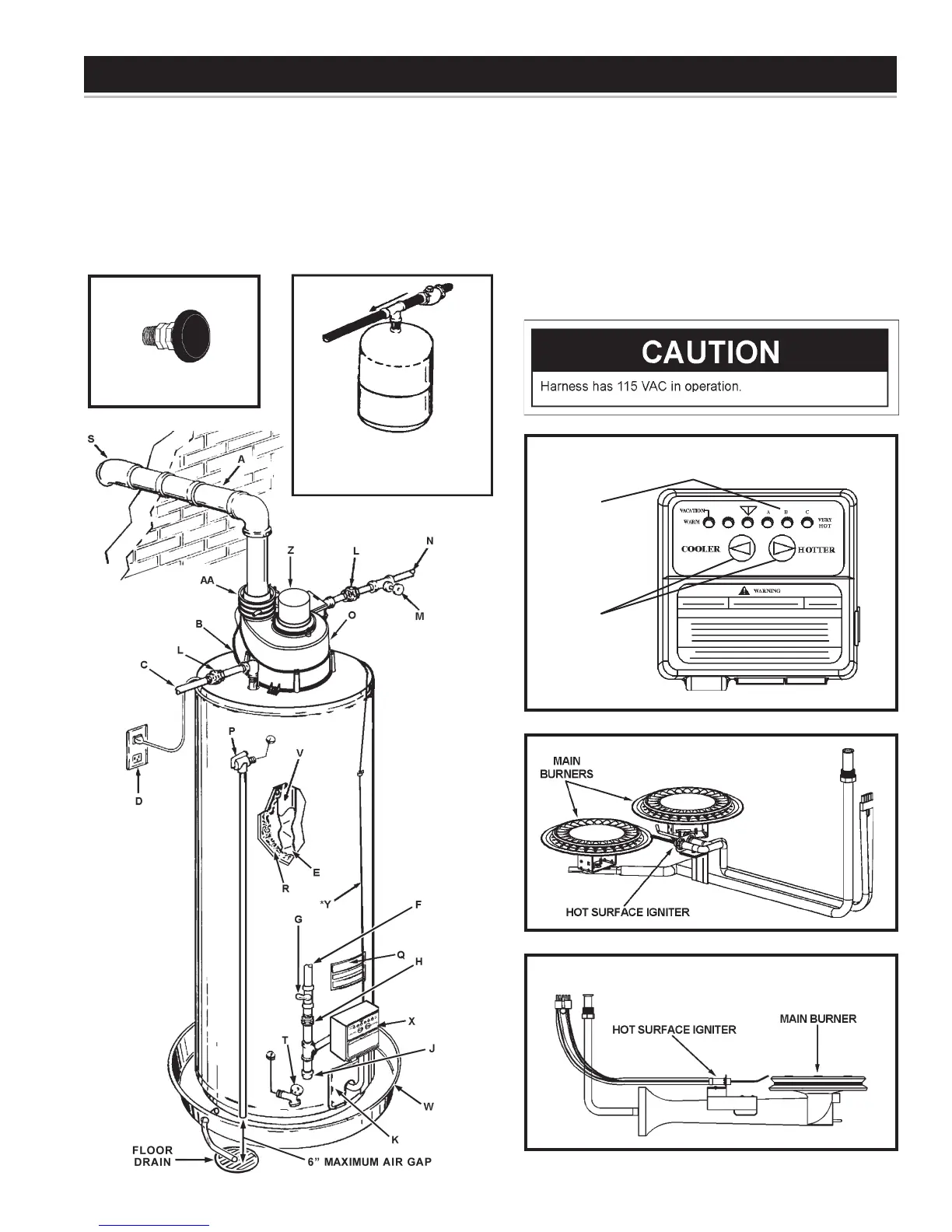
(A) VENT PIPE
(B) ANODE
(C) HOT WATER OUTLET
(D) OUTLET (120 VAC)
(E) FLUE BAFFLE
(F) GAS SUPPLY
(G) MAIN MANUAL GAS
SHUT OFF VALVE
(H) GROUND JOINT UNION
(J) DIRT LEG
(K) OUTER DOOR
(L) UNION
(M) INLET WATER SHUT
OFF VALVE
(N) COLD WATER INLET
FIGURE 1.
REPLACEMENT PARTS AND DELIMING PRODUCTS
Replacement parts and recommended delimer may be ordered
through authorized servicers or distributors. Refer to the Yellow
Pages for where to call or contact the water heater manufacturer
at, 500 Tennessee Waltz Parkway, Ashland City, TN 37015. When
ordering parts, provide complete model and serial numbers (see rating
plate), quantity and name of part desired, see Figure 1. Standard
hardware items may be purchased locally.
(O) INLET DIP TUBE
(P) TEMPERATURE AND
PRESSURE RELIEF VALVE
(Q) RATING PLATE
(R) INSULATION
(S) VENT TERMINAL
(T) DRAIN VALVE
(U) IGNITER AND MAIN
BURNER
(V) FLUE
(W) METAL DRAIN PAN
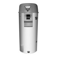
(X)
GAS CONTROL/THERMOSTAT
(Y) CONTROL HARNESS*
(Z) MOTOR & BLOWER
(AA) CONDENSATE FITTING
(U) PROPANE GAS MAIN BURNER
WITH IGNITER ASSEMBLY
(SIDE VIEW)
TYPICAL INSTALLATION
INSTALL THERMAL EXPANSION
TANK IF WATER HEATER IS
INSTALLED IN A CLOSED
WATER SYSTEM.
VACUUM RELIEF VALVE
*INSTALL PER LOCAL
CODES
(U) NATURAL GAS MAIN BURNER
WITH IGNITER ASSEMBLY
TEMPERATURE
ADJUSTMENT
BUTTONS
TEMPERATURE
INDICATORS
(X)
GAS CONTROL/THERMOSTAT
 Loading...