Chapter 4 – Start-up Procedure
4-2 ACH 400 with Electronic Bypass User’s Manual
Electronic Bypass
Jumper, Switch and
Pot Settings
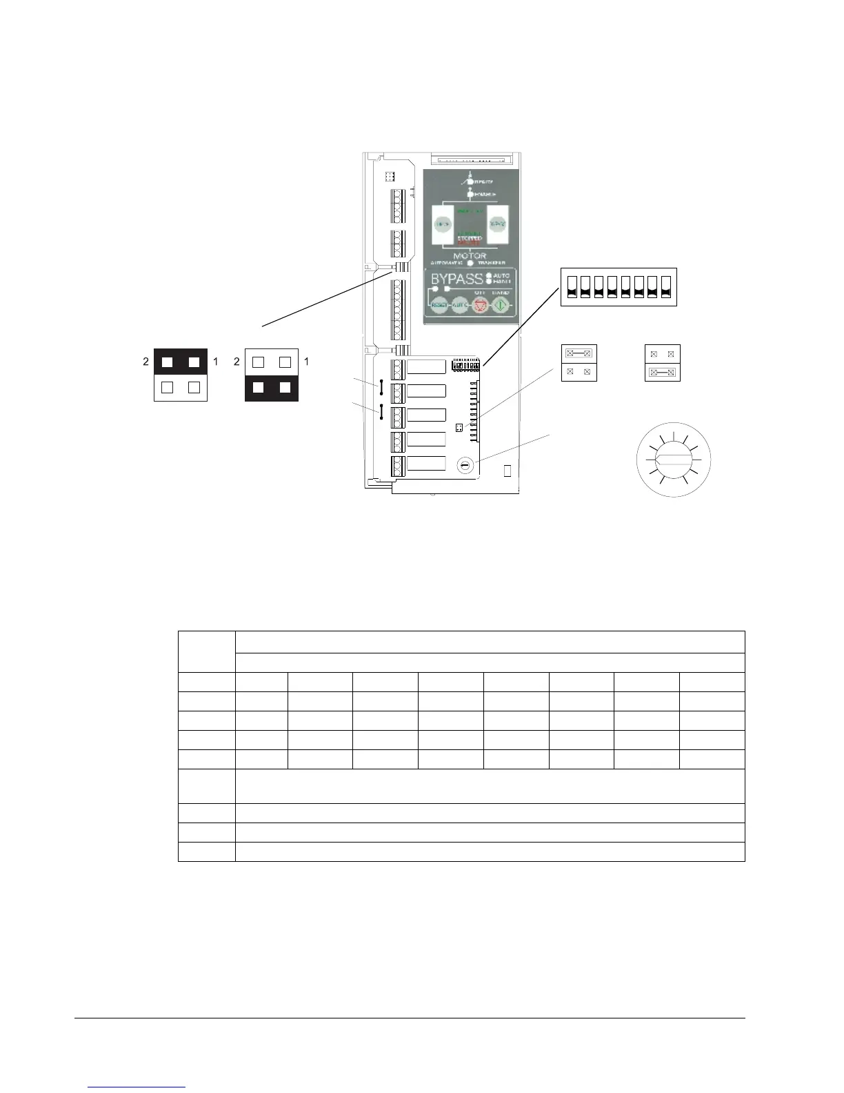
Figure 4-1 shows the locations of the jumpers, DIP switch and potentiometer
on the Electronic Bypass control board. The functions and settings of these
items are explained in the following paragraphs.
Figure 4-1 Electronic Bypass Control Board
DIP Switch Settings The DIP switch is used to configure the bypass overload protection and
enable the automatic bypass feature.
Match the DIP Switch Codes to your drive model using Table 4-3.
Table 4-1 DIP Switch Settings
User Override Jumper In the unlikely event of failure in the bypass control electronics, the user can
put the bypass in the drive mode by moving jumper J2 to the position as
shown in Figure 4-1. Power must first be applied to the system before placing
the jumper in the User Override position. When the jumper is in the User
Override position, the Drive contactor is energized and the Bypass contactor
is deenergized. The contactors are not controlled by the Electronic Bypass
keypad when the bypass is in the User Override mode.
Switch
Switch Setting Configurations
Overload protection configuration for frame size
Code A B C D E F G H
8 (A0) OFF ON OFF ON OFF ON OFF ON
7 (A1) OFF OFF ON ON OFF OFF ON ON
6 (A2) OFF OFF OFF OFF ON ON ON ON
5 (A3) ON ON ON ON ON ON ON ON
4 (A4) OFF/ON = NEMA Class 30/NEMA Class 20
overload trip curve
3 (A5) OFF/ON = Automatic Reset OFF/ON
2 (A6) OFF/ON = Underload Protection Feature OFF/ON
1 (A7) OFF/ON = Automatic Bypass Feature OFF/ON
ON
1 2 3 4 5 6 7 8
Dip Switch
Jumper J2
Normal
Setting
User Override
Setting
50
1
0
0
0
Potentiometer
R63
R64
Jumper
Wires
Jumper J3
110 VAC
POWERED
I/O
24 VDC
POWERED
I/O
 Loading...


